ShapeMaster User Guide
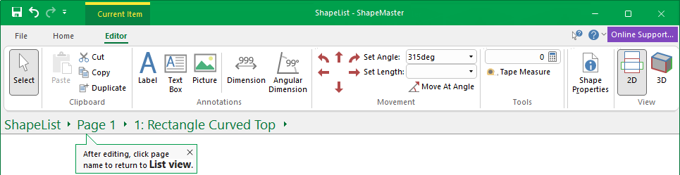
This command ribbon is provided when you select a shape/item (e.g. Rectangle) using the breadcrumbs bar, which is used to navigate pages, shapes and parts.
 |
To locate information about any commands or tabs,  click on the area of interest on ribbon image above.
The shape will be displayed in 2D View but you can use the View commands to easily open the Shape Properties.
See also Drawing Tools for more information about customising object properties.
Changes to the Select tool. Click on this link to Select for more details.
This Group of commands allows you to Cut, Copy, Duplicate and Paste.
This command lets you place text into a job/drawing. You can select text size, font and so on, simply...
This command lets you insert text inside a rectangular box into a drawing. The text auto-wraps to fit inside the box, and if there is too much text, it is clipped to the box. To do this follow the instructions above for Label. To place a text box on a drawing, you need to specify two points which are opposing corners of the rectangle. Just select the text box tool, click on the drawing while holding the button down, then drag the mouse to form a rectangle. You can then move the text box and resize it exactly to your needs.
This command lets you insert a picture directly into a drawing. Bitmaps are picture files with an extension of "bmp". You can create, view, and edit these in 'Paint', which comes with a standard install of Windows. Almost every other image program will let you view bitmaps as well. The Bitmap tool can be used to place one of these images on a drawing, for example, you may place your company logo on a drawing template. As well as regular bitmaps, the tool also supports DIB (device independent bitmap) and compressed RLE (run length encoded) images.
Dimension tools are used for measuring different parts of your shape and the following associated dimensioning commands allow you to easily insert and place dimension lines.
The dimension tool works in a 3 click process. Enable the command by clicking on the Dimension  button on the ribbon, then...
When you drag to place, you are able to set the dimension lines in various locations, just by holding down the mouse key and dragging until in required position.
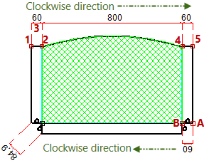
The dimension measurement displayed is dependent on direction of placement - notice that the bottom dimensions are displayed upside down. You can re-dimension or change the Angle of the Dimension Properties.
Once the first dimension is placed, you can simply keep clicking to add more dimensions. In the example, we have continued clicking (4 and 5) to measure to the end of top of the shape.
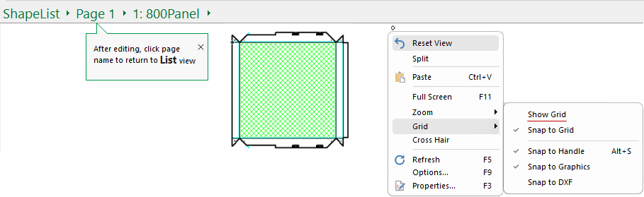
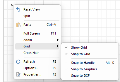
If manually zooming in 2D View, before using the wheel to zoom in, click on area that you want to get a closer look at. If you loose focus, use the Reset View and try again.
Dimensions added using the Current Editor, will display in the preview pane. Turning on Show Grid and Snap to Handle may also be useful.
To end, simply click on another command (e.g. Select)
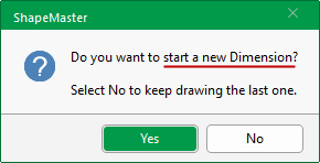
To start a new dimension, click on the Dimension command icon and select 'Yes' to the presented message.
The dimension measurement displayed is dependent on direction of placement. In the above example, the dimension between points A and B is upside down.
This means dimensions attached to objects in the drawing will resize automatically when the object is changed or moved to a different location. Turning on Snap to Grid (useful with Cutouts) or Snap To Handle will ensure that the dimensioning command tool will know which shape handle they are meant to be associated with.
To delete a placed dimension, simply select it (it will display in light blue) and hit the keyboard Delete key.
This is a drawing tool and the colour and style of the dimension lines can be changed and, if required, saved for future use - see Dimensions Property Sheet.
See the following for detailed discussions:-
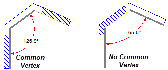
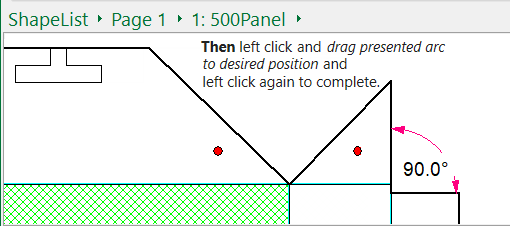
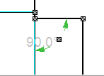
The Angular Dimension tool allows you to dimension...
Then after the first one or two clicks (depending on where you click) there is a rubberband movement of the arc dimension line until you click to place.
 command icon.
 ) and the nearest pair of adjacent sides are auto selected when you are outside snap distance.
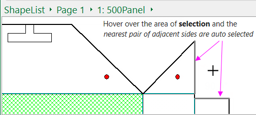
To select sides that are not adjacent, as in the example above, you use two clicks.
To delete a placed dimension, simply Select it (it will display greyed out as shown) and hit the keyboard delete key.
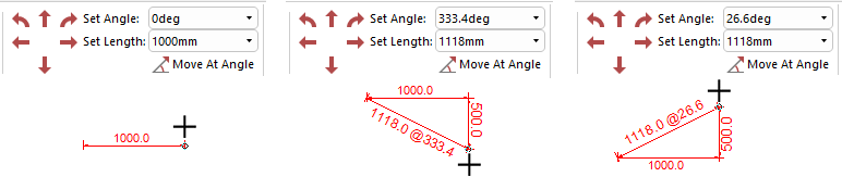
For full discussion, click on the link to Movement topic.
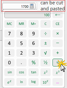
You can type directly in the edit box or click on the  to open the calculator application, as shown. When the equal sign is clicked, the result is displayed in the edit box e.g. 1700. The resulting number can be cut and pasted between the calculator and text boxes in ShapeMaster, so you do not need to write down results and type them back in. It a handy tool and takes up next to no space.
Pressing the  button will open the Standard Windows calculator.
If you use this command and nothing happens, it most likely means that you do not have the calculator installed.
Formulas can also be entered directly into edit boxes as shown here.


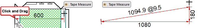
Allows you to draw a line between two points while displaying the horizontal offset, vertical offset and total distance between them.
First, select/turn on the Tape Measure and then...
When you release the mouse button, the distance between the two points and angle are copied into the Set Length and Set Angle edit boxes for convenience.
Allows you to Format the current item which could be a shape or other object. (Same as selecting Format ... from the right click menu).
2D View is strictly for the placement of entities, such as annotations, text boxes, labels and dimensions and do not appear in 3D views.
When in 2D View, before using the wheel to Zoom in, click on area that you want to get a closer look. If you loose focus, use the Reset View and try again.
For full discussion refer to topic on Zoom.
Clicking on this command button will take you to the 3D Tools | Display tab.