ShapeMaster User Guide
The Cutout feature allows customers to add lettering and decorative cutouts to a shape, by machining existing DXF files of outlines in repeated sets of up to five (A to E) individual outlines. ShapeMaster will then seamlessly integrate with EzyNest to achieve the desired result.
A Multi Shape allows the addition of up to 5 sections and therefore has an additional page called Sections.
The section does not need to be selected on the Sections page to have custom cutouts applied as Origin buttons are used to designate where cutouts are placed.
 Watch the video below which demonstrates how to add pre-defined cutouts using DXF files. [2:22 mins]
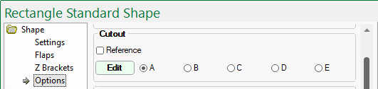
Radio buttons (A to E) allow you to select repeated sets of up to five DXF file for machining.
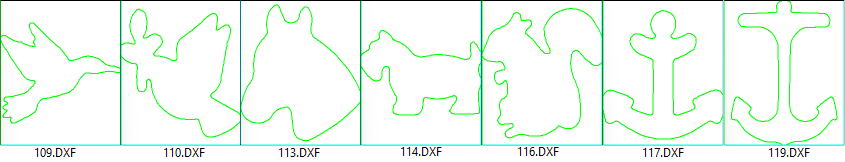
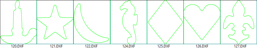
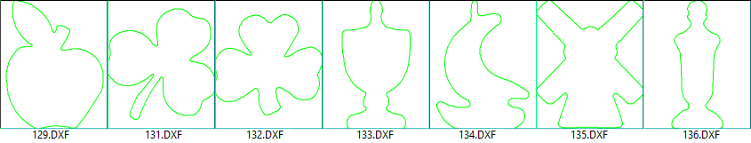
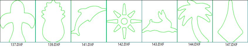
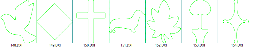
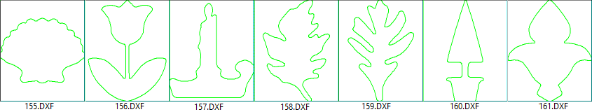
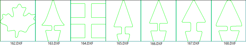
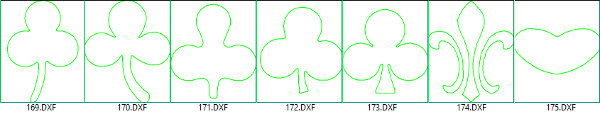
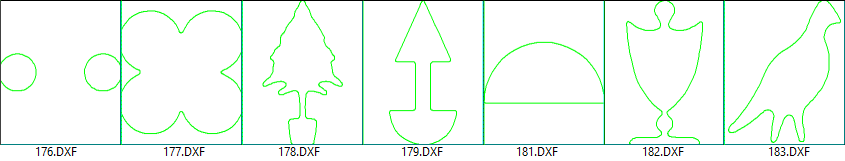
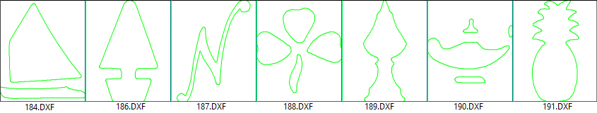
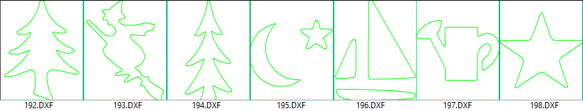
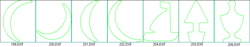
For a complete list of supplied DXF images together with their reference number, see DXF Cutout Samples below.
Click to view another example using a Repeat Cutout
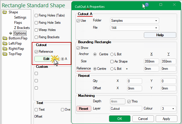
Pressing the Edit button will open selected Cutout Properties dialog.
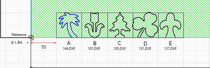
In the example above, five different cutout outlines have been applied, with the...
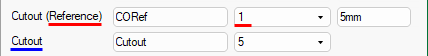
The colour of the Reference point for these examples has been set to red (1) and cutout to blue (5) for clarity - see available DXF Colours.
Click on image to view Reference point in Machining Preview
The Reference point in the preview pane is only shown when Machine View is selected on the Shape > Settings page - click image to view.
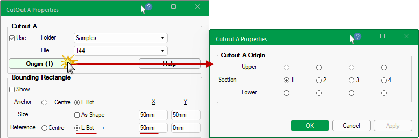
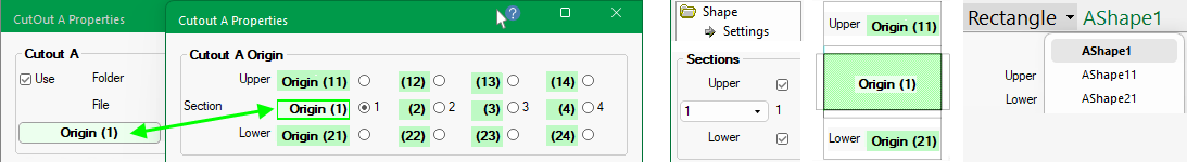
In the above example, an extra button called Origin is displayed indicating that a Shape can have (or has) multiple sections.
The Origin button states which section is being currently looked at i.e. Upper Sections begin with (1n) and Lower Sections begin with (2n).
If there is only one (1) section then an Origin button will not be displayed and is therefore not discussed in this topic.
See discussion on Sections and Origins buttons for a HowTo on 'Adding Sections' and applying cutouts to a section by using the Origin button.
Watch the video below which demonstrates how to add pre-defined cutouts using DXF files. [2:22 mins]
The Use checkbox needs to be ticked to apply a Cutout, as shown. Then, using the Folder and File drop lists, select a DXF file.
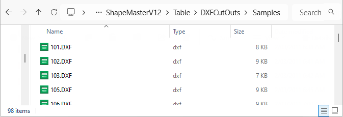
Sample DXF files can be located in <your ShapeMaster folder>/Table/DXFCutouts/Samples folder but you can create as many Folders/Files as you require in the DXFCutouts folder for selection.
Folder and File location
The contents of these DXF files are discussed later in this topic and can be used, renamed and/or customised.
In the following discussion, we are going to use the .../Samples/144.dxf file - see DXF Cutout Samples below, which shows that 144.dxf is a 'tree'.
The Show Reference Point option allows you to see where the cutouts are positioned with reference to a given point on the shape, either Centre or L Bot (bottom left).
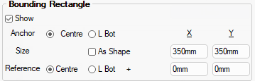
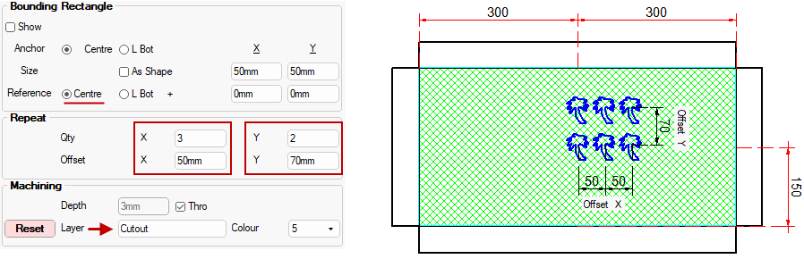
The Bounding Rectangle defines the extremes the cutout can fit into.
Show checkbox is used to turn on/off the boundary line.
The Size of the DXF can be set to fit As Shape or an X/Y dimension.
Anchor refers to the datum point, either Centre or Bottom Left by using the radio buttons.
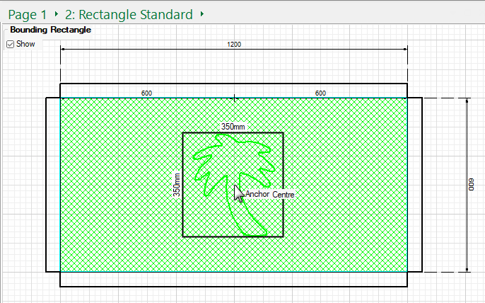
Example shows settings as per above i.e. Show Boundary Rectangle, Anchor DXF to Centre with a Size of 350mm x 350mm.
- Click on image to view an example of Anchor Centre with the option Size As Shape enabled.
- The Reference Point will only be displayed if the part (AShape) is selected on the Breadcrumbs Bar.
- Show Grid has been turned on and Dimensions added for clarity.
Click to view DXF file set to Size As Shape with Show turned off
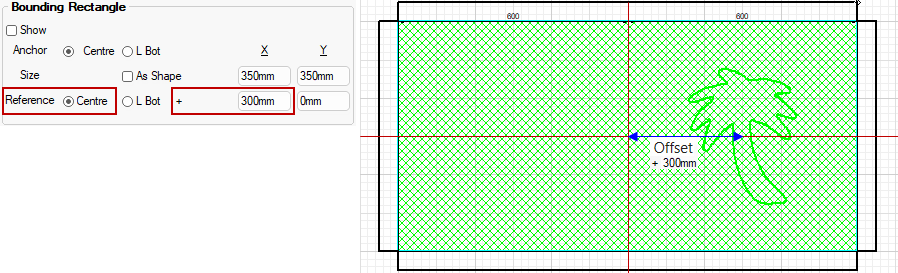
Reference is where on the part the anchor point is aligned to, which in this example is Centre.
- Then you can Offset your cutout a specified distance from the reference.
The cutout outlines are placed within Bounding Rectangles which allows them to be sized.
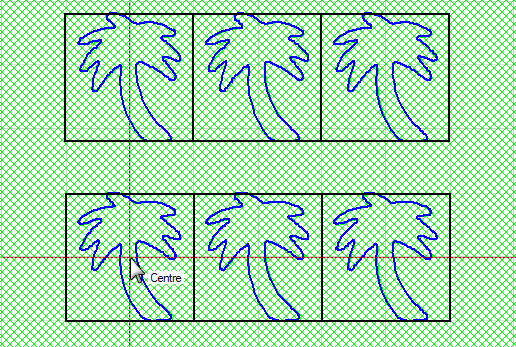
The Repeat options allow multiple cutouts at a specified Offset.
The position of the rectangle (Centre or L Bot) is defined as an Offset from the Reference Point, which in this example is 'Centre'.
Click to view another example of Offset used with Reference L Bot
When in 2D View, before using the wheel to Zoom in, click on area that you want to get a closer look at. If you loose focus, use the Reset View and try again.
In the example above, we have used Dimensioning in the Current Editor which is displayed in the preview.
The Depth of each cutout can be controlled by either selecting a required Depth or using the Thro option, as shown above, which automatically adjusts with the thickness of the material.
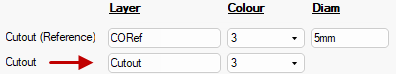
The default Layer name and DXF colour can be specified in the Drawing Properties. There is also the layer name for the Reference point (which can be ignored in the actual machining).
In the above example, the Colour was changed from 3 (green default below) to 5 (blue) - pressing the Reset button will revert to the default.
Setup > Machining page defaults : Click to Expand
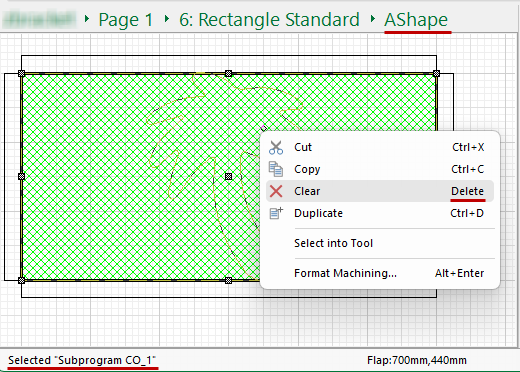
To delete a cutout, first select the part using the Breadcrumbs Bar (in this example, AShape) - this will make the Machining Editor commands available.
Then (2) select the cutout and use the right click menu to Clear/Delete (as shown).
Click to Expand
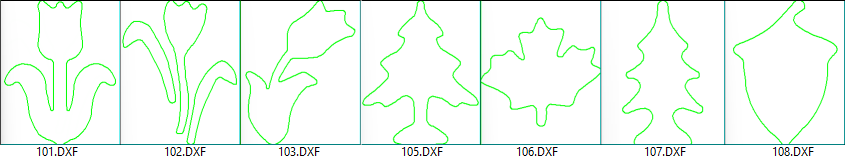
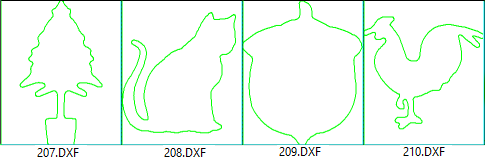
The following DXF's are supplied in the ...DXFCutouts/Samples folder.
You can create as many Folders/Files as you require in the ...Table/DXFCutouts folder for selection.
A Minute with Mike : This video demonstrates how to add pre-defined DXF cutouts, using our supplied sample files but you can create your own.
This video uses a different CabMaster Software™ application but the process is the same.
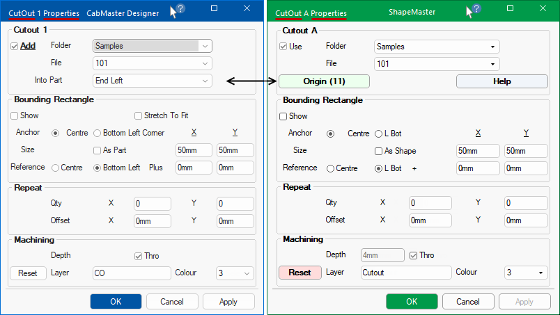
Click here to compare the properties sheet used in this video to the ShapeMaster properties sheet.
As shown here, the CabMaster CutOut Properties sheet is similar to the ShapeMaster CutOut Properties sheet.
The only real difference is that CabMaster allows you to add cutouts to cabinet parts but the process is the same.