ShapeMaster User Guide
The Shape > Settings page is common for all shapes, irrespective if Multi Shape or Standard.
In this topic we will discuss the Settings page for the Rectangle per group header (underlined in example images).

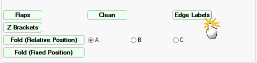
For a quick link to specific discussions regarding the following image, click on the relevant button.
This button  displays the name of the shape and clicking on it will open the Local Properties dialog.
Details displayed here restate the Name of the shape (discussed further below) and other relevant details such as...
Name is the Label Name in List View and can be enabled for display purposes.

Param 3 are the dimensions including flaps - Click to view Local Properties
Param 3 for a Standard Shape is Width x Height of shape, whereas with Multi Shapes 'Param 3' includes flaps (click on image).
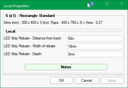
Local Properties are user defined variables that can be referred to in custom machining tables and reports.
At the Catalog/Drawing level, up to 25 Definitions can be enabled and named in the Setup > Local Properties.
Qty is the number of boxes to be cut (one dxf is created, this quantity appears in the dxt).
dxf and dxt location and example
This is for explanation only as you will never have to check anything here.
The DXT for the shape shows that it has a quantity of 2 even though there is only one DXF i.e. rectangle_1.dxf
The Name of the shape can be amended. Changing this will update the...
Dimensions for Height and Width of each Section of the shape can be amended independently.
The Standard Rectangle has only one section and Height and Width is nominated on the Settings page, as shown.
An additional Shape button
allows you to select another shape format. Note that when a specific Shape is used, other (unrelated) sizing options are disabled - see following examples.
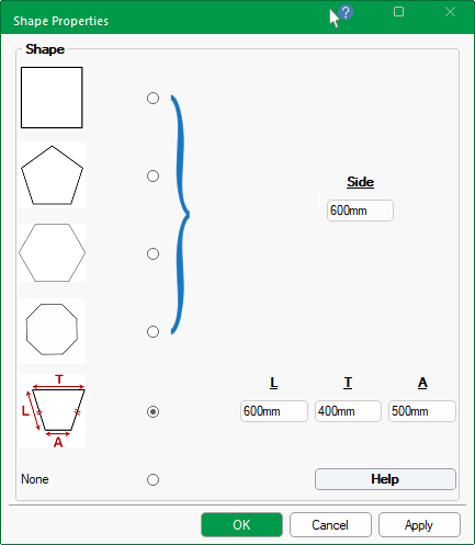
Shape button - examples of other shape formats that can be selected.
When the Shape button is pressed, the Shape Properties dialog allows you to create a shape i.e. Square, Pentagon, Hexagon and Octagon, using the length of Side.
The Trapezium is created using the length (L) and widths (T and A).
None reverts to default shape e.g. Rectangle.
When a Shape is used, other options are disabled - Click to view
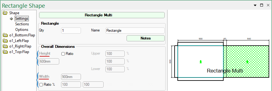
Multi Shapes allow the addition of multiple Sections (up to 5 sections allowed - see discussion below).
As each section can be configured separately, the Overall Dimensions are normally preset defaults and greyed out, as shown. However, these can be overridden by ticking the Ratio checkbox for Height and/or Width.
If the defaults are overridden by ticking any of the Ratio % checkboxes , you can configure each available section on the Shape > Sections page - see the topic on Dimensions Overall Section.
The Width allows for percentage change for each section (up to 5) and corresponding edit boxes allowing Ratio % entry.
The Multi Shape above only has 2 sections (shown in the preview) and therefore only two edit boxes for Ratio % (click on image to view example of use).
Click to view Width Ratio % for rectangle with 5 sections and example of use.
See the topic on Dimensions Overall Section for a full discussion on dimensions and other related options (such as those shown here).
For a quick link to specific discussions on any of the following, click on the relevant button.
This group of options are only available with Multi Shapes as Standard Shapes allow only one (1) section.
The default is for the configuration of one (1) section. The drop list allows up to 5 sections to be added (click on image), with the provision to add Upper and Lower sections using corresponding checkboxes.
The Shape > Sections page allows you to Configure each section of the selected Shape.

Click to view preview of shape with 5 sections selected with upper and lower.
The Slope options are only available with Multi Shapes.
The Slope can be enabled for the Top and/or Bottom of the shape and is applied to Height i.e. Left and/or Right.
Example 1 : This shape has only one (1) Section and the slope enabled only for the Top Left.

Top and Bottom checkboxes have both been enabled.
The Heights dimensions are unchanged but the Bottom checkbox has also been enabled.
If there are multiple sections, then the slope is applied across all specified sections, as shown below.
Example 2 : This shape has three (3) sections and the Width for each section can be amended using the additional edit boxes provided.
The Heights however, are only configurable for the Left and/or Right of all sections.
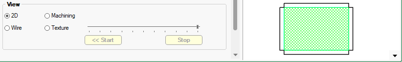
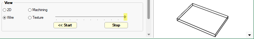
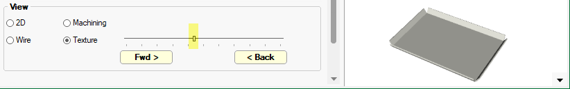
Quickly change the Preview by using the radio buttons.
Shown here is machining for the current component in 2D as it would look going out to machine.
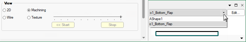
The Machining view option allows you to select individual sections using the drop list, as shown.
3D Views support an automatic Play buttons which can be used to slowly folds the part from flat to completely folded and back again as an animated option.
For Multi Shapes this options is available on the Sections page.
For the Polyshape this option is available on the Border page
On the Settings page enable the DXF radio button. Then on the Border page, press the Select DXF button which opens window explorer, allowing you to search for required DXF.
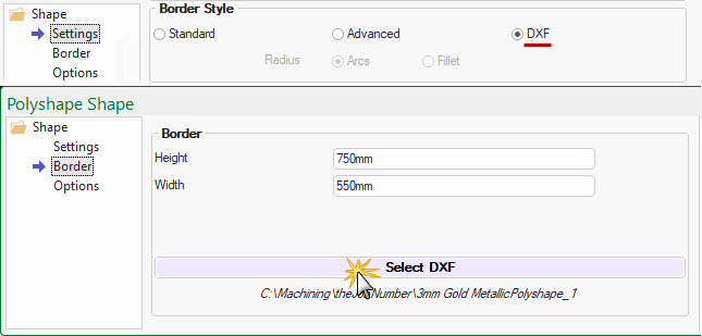
Import a 2D DXF file as your border for the Rectangle and Rectangle Multi parts.
This lets you import any shape. You cannot always add flaps to the parts but you can add holes, routes and slots in machine editor.
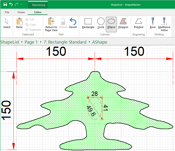
Example of Machine Editing of DXF
In this example, we have used a Rectangle Standard, with no flaps, and imported a tree dxf and used it for the border. A hole has then been added in the centre, as shown. Click on image to view the options and DXF file selected.
Click to view Settings page and preview pane (textured)