ShapeMaster User Guide
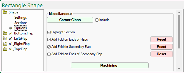
The Shape > Options page is similar for all shapes, irrespective if Multi Shape or Standard.
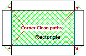
This group of options provides the ability to define default corner clean depths and set the default of fold lines on the end of flaps.
Corner Clean parameters, as shown, can be changed at Shape level by clicking on the Corner Clean button.
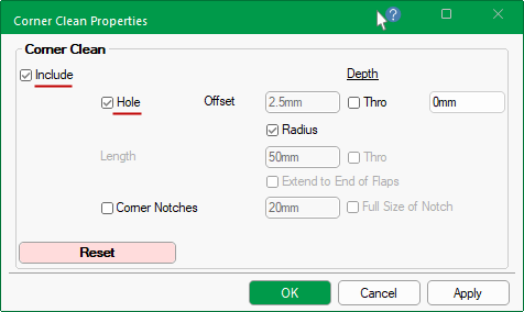
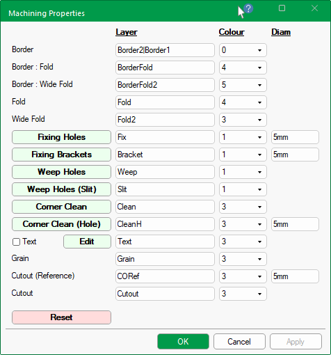
The Include check boxes are enabled by ticking either the checkbox on the Options page shown above or on the Properties dialog, shown below.
Enable the Hole checkbox to create a hole on each corner.
The Depth of the hole can be controlled by either entering a required depth value or ticking the Thro checkbox, which automatically adjusts with the thickness of the material.
The Offset can be controlled by either entering a required value (e.g. 2.5mm) or by ticking the Radius checkbox, the Corner Clean Hole will use the radius as the offset.
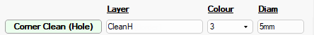
The Diameter of the Hole is set on the Setup > Machining page of the the Drawing properties, unless overridden at Shape level by using the Machining button.
Use the Reset button if you want to reset the values back to the Drawing properties - see Setup Corner Clean.
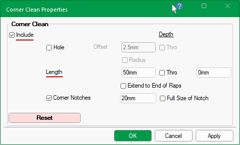
Flaps
If Hole is unticked, then the corner cleanout will add a continuous (triangular) toolpath into each corner to allow a small tool to get in and clean the corner out.
The distance this continues along the edge of the shape is based on the Length setting. If the Extend to End of Flaps checkbox is ticked, then the distance will automatically adjust to the full size of flap.
The Depth of the toolpath can be controlled by either entering a required depth value or ticking the Thro checkbox, which automatically adjusts with the thickness of the material.
Corner Notches
The Corner Notches checkbox allows separate control to turn on/off this for notches.
The Length can be specified or by ticking the Full Size of Notch checkbox, the length will automatically adjust the distance the toolpath continues along its edge to the fill size of the notch.
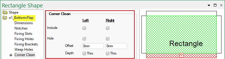
The Corner Clean can be further controlled on individual flaps, thereby overriding the settings on the Shape > Options page discussed above.
The following image shows that a Corner Clean hole is selected for the Bottom Flap.
Click to Expand
The Machining button  will open the Machining Properties.
Clicking on the Reset button will reset these options to defaults set in the Drawing properties - See Setup Machining.
Click to view Machining Properties
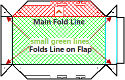
This is the shading (as shown below in green) to highlight the selected section in the preview pane.
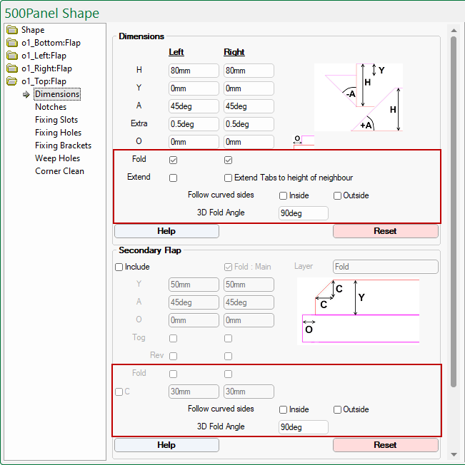
A flap can have a Main Fold Line which attaches to the rest of the shape.
There are also fold lines on the Secondary Flap (Left and Right), all of which can be controlled independently.
A 3D Fold Angle selection is also available for both the Main and Secondary Flaps.
Independent control available for each Flap
Override the defaults set on the Shape > Options page by selecting the required Flap > Dimensions page.
At Drawing level defaults are set but can be overridden at Shape level.
Use the Reset button if you want to reset the values back to the Drawing properties - see Setup Defaults.

Click to view Materials Manager setup of this material - Note: 'Highlight Section' has been turned off so that the grain direction can be clearly seen
The Material drop list allows you to override the Drawing default setting on the Job Details > Materials page.
Additional information pertaining to the material are displayed beneath i.e. if it is defined as grained, thickness, fold details and code (if available).
If the material is defined as grained, each shape has the ability to be nested with the grain in a chosen direction.
Even though the Material Manager definition only allows X and Y grain (i.e. 0 and 90 degree). The shape options allows you to specify the exact direction on each part using the radio buttons i.e. Up or Down or Left or Right.
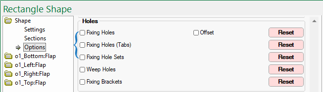
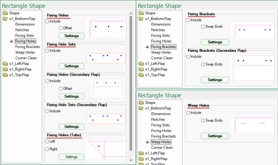
The Setup > Holes page of the Drawing Properties allows you to place securing holes around the edges of the tabs on shapes.
These are reflected on the Shape > Options page which can be overridden to set the default for every flap added. Use the applicable Reset button to set back to the Drawing default if changes are made here.
Which edges to drill holes in can be selected per flap, as they are added to the job.
The presence and location of holes can be edited by using the applicable Settings buttons provided.
For more information on fixing holes, follow the links provided above.
Follow these links for more information on Fixing Brackets and/or Weep Holes.
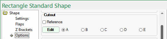
The cutout feature allows customers to take existing DXF files of outlines, and machine repeated sets of up to five (A to E) different outlines on any shape.
This allows you to add lettering and decorative cutouts to a shape which ShapeMaster seamlessly integrates with EzyNest.
Follow the link for a complete discussion on Cutouts.
Sample DXF's are supplied in the ...DXFCutouts/Samples folder - follow this link to see images of these.
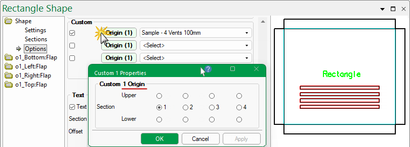
Custom Tables are very useful additions to the capability of ShapeMaster, allowing you to develop your own custom machining and apply it to various parts of shapes.
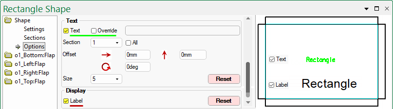
The Text checkbox for both Standard and Multi Shapes allows you to turn on/off the name of the part being displayed in the preview pane and editor modes, and/or machined onto the part. It can also be customised.
The default text is as Shape Name that can be amended on the Shape > Settings page - follow link for more on Name.
Click to view in Machine Editor mode
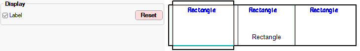
The Text and Label feature are different even though, as shown above, they may display the same detail if no custom changes are made.
For a detailed discussion on Text Properties, refer to the topic on Setup > Machining.
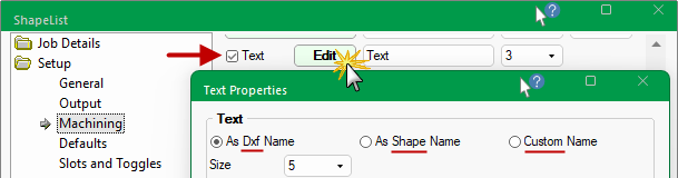
The Text Name property available on each part can be machined onto the part or just displayed in the DXF (by not associating a toolpath to the layer in EzyNest).
The Layer Name, Colour and Text Properties can be defined by using the Machining button on the Shape > Options page or at Drawing level as shown.
For a detailed discussion on Text Properties, refer to the topic on Setup > Machining.
If changes are made to the Text group of the Shape > Options page, the Reset button will set all options back to the Drawing Properties.
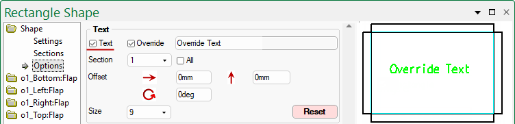
To enable this feature, tick the Text checkbox at either Drawing level or Shape level.
Tick the Override checkbox to allow text to be typed into the provided edit box, as shown.
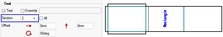
This allows you to override the part name with your own text, while still keeping the part name. Display your own text, size, angle and offset on each section of a part, if required.
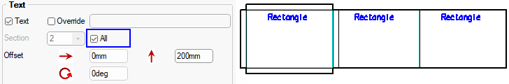
On Multi Shapes, there is also the ability to move text between sections (or have the text on All Sections).
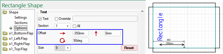
Text can be offset left/right or up/down at any desired angle. The Size drop list allows you to change the font size.
In this example the shape name has been moved to the Left 350mm from the centre i.e. -350mm and rotated 90 degrees.
If the shape has more than one section then the text can be designated to display on...
The shape Label name will be the Name entered on the Shape > Settings page. If enabled, this will only display once (on the middle section).