ShapeMaster User Guide
The Setup > Defaults page of the Catalog/Drawing Properties allows you to set the height of flap and notch defaults, as every job/drawing involves different dimensions.
To reduce the need to make constant changes, it makes sense to set up Catalog default settings.
At Shape level, flap and notch parameters are dependent on values set here in the Drawing Properties and are therefore also discussed in this topic.
 click on the area of interest on image below to locate relevant information.
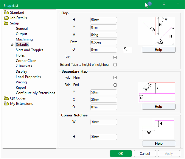
These options in this group of options allow you to set default dimensions of flaps and whether to include a Fold or not.
These can then be overridden on the Dimensions page of the selected flap of the Shape Properties, as shown in the example images below.
The Reset buttons on the Shape Property page can be used to revert the settings in the selected group back to the Drawing Properties.
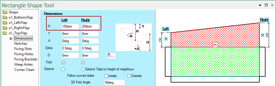
Sets the initial Height of flaps.
Override this setting on the Shape Property page to create angled flaps, as shown.
Use the Y values to add some clearance, as it offsets the tab from the edge of the flaps.
In this example, the Left flap of the shape has a Y offset of 30mm.
Sets the Angle of the flap Edge.
Override this setting in the Shape Properties to control the angle of Left and/or Right flaps, as shown below.
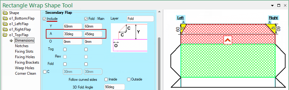
Angle of Secondary Flap on Shape
If Include is ticked, you can set the Angle of the secondary flap edge in the Shape Properties.
In this example, the angle of Left and/or Right secondary flaps have been 30° and 45° respectively.
Increase the angle of the flap edge by a set Extra degree value. Useful to add a small amount of clearance to a corner (e.g. 0.5 to 2 degrees).
In this example, the angles have been increased by an extra 0.5° i.e. the Left edge is 45°+ 0.5°= 45.5° and the Right edge is 25°+ 0.5°= 25.5°
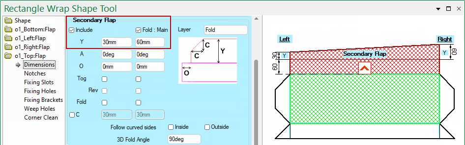
Use the O values to add clearance by offsetting the flap ends.
The example shows the Shape Properties with the Offset set for the Left end by 30mm and on the Right end by 60mm.
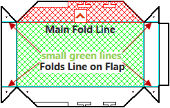
A flap can have a Main Fold Line attaches to the rest of the shape, but also fold lines on the Left and Right or the Flap. All of which can be controlled independently - Base Shape Introduction.
The Extend check box is to do with lining up the extra flap pieces on the end of a flap.
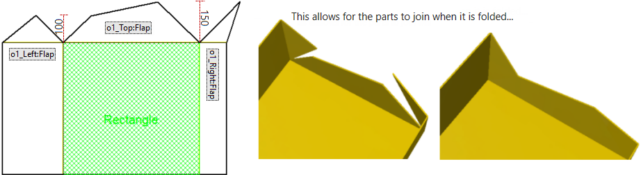
In the example below the height of the Top Flap is 100 on its left and 150 on its right.
The Right Flap is 100, but notice how its angled part is extended.
The Left Flap is 150, but notice how its extra flap is reduced. The extra flap pieces at the side are called "Tabs".
Set the default height of secondary flap dimensions, which are not enabled at Shape level unless the Include check box is ticked.
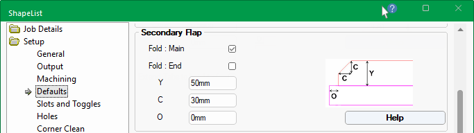
Sets the Height of the secondary flap which sits above the initial flap, as shown.
On the Shape Property page the Include checkbox has been ticked and Y values have been overridden to create an angled secondary flap.
Click to Expand
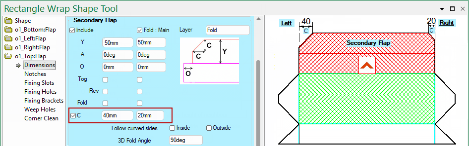
Sets the default length of the chamfer, which will add a 45° chamfer.
On the Shape Property page, enable by ticking the C check box. This will allow you to override the default settings, as shown.
Use the O values to add clearance by offsetting the secondary flap ends.
The example shows the Shape Properties with the Offset set for the Left end by 50mm and on the Right end by 20mm.
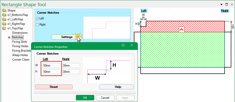
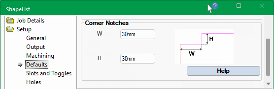
Sets the default width and height of notches.
On the required Flap > Notches page of the Shape Properties you can override the default settings, as shown below, for the Left and/or Right of flap.
Clicking on the Settings button opens a property sheet, allowing you to enter the new Width and Height dimensions.