In This Topic
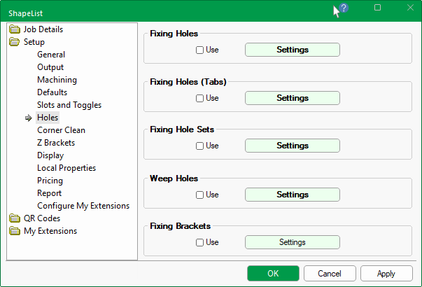
The Setup > Holes page of the / Properties allows you to place securing holes around the edges of the tabs on .
Which edges to drill holes in can be selected per , as they are added to the job (and/or saved in the catalog). The presence and location of holes can be edited by using the Settings buttons provided.
At level, hole parameters are dependent on values set here in the Properties and are therefore also discussed in this topic.
Securing/fixing holes can be placed around the edges of the flaps on the shapes to allow for mounting to wall.
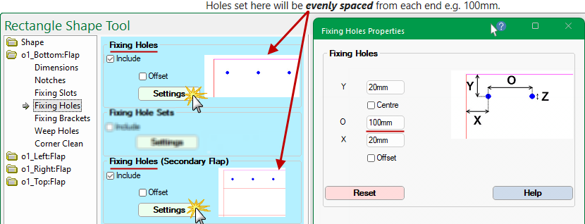
Holes set here will be evenly spaced from each end e.g. 100mm.
Only evenly spaced or individually controlled holes should be enabled for the same job.
However, if both are enabled for any reason, then the job will default to evenly spaced.

At Shape level, fixing hole parameters are located on the Shape > Fixing Holes page.
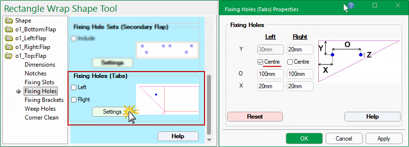
On the Shape > Fixing Holes page of the tick the Include to enable evenly spaced holes on the main flap and, if required, the Secondary flap.
If amendments are required, press the Settings button to open the corresponding .
- Use the Reset button if you want to reset the values back to the properties.
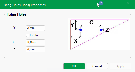
Z : Hole Diameter
Diameter of the hole. The actual diameter of the hole will depend on the tool chosen in .
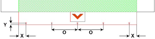
Y : Distance from Edge
Distance from the centre of the hole to the tab edge i.e. distance from external edge.
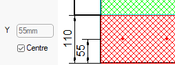
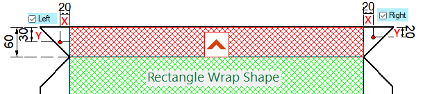
Ticking the Centre checkbox will place centre of hole in middle of tab, as shown.
O : Max. Distance Apart
One hole is placed at the end of each tab, then as many holes as required are placed between these two depending on the distance apart.
No two holes will be greater than the distance selected here i.e. average distance between holes up to its value.
X : Distance from Ends
Distance the end two holes are from the end of the tabs i.e. value from each end.
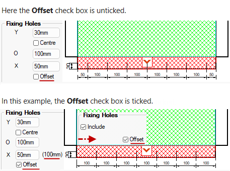
The Offset will adjust the end holes by the value of X.
The Offset will adust the end holes by the X value.
Securing/fixing holes can be placed on the tabs of flaps.
Holes set here affect the controllable holes on the connector tabs.
At Shape level, hole parameters are located on the Shape > Fixing Holes page.
On the Shape > Fixing Holes page of the
Z : Hole Diameter
Diameter of the hole. The actual diameter of the hole will depend on the tool chosen in .
Y : Distance from Edge
Distance from the centre of the hole to the tab edge i.e. distance from external edge.
Ticking the Centre checkbox will place centre the hole to middle of Tab in Y direction. (See above Left).
O : Distance Apart
Distance between multiple holes, if able to fit on Tab.
X : Distance from Fold
Distance the hole is from the fold of the tab.
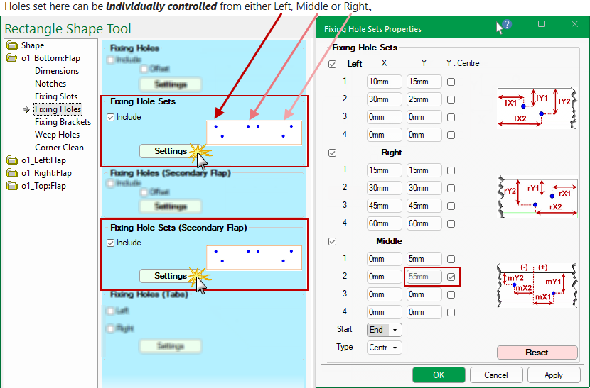
Sets of securing/fixing holes can be placed around the edges of the flaps on the shapes.
Holes set here can be individually controlled from either Left, Right or Middle.
At Shape level, hole parameters are located on the Shape > Fixing Holes page.
If you made amendments and want to reset values back to the Properties, simply press the Reset button.
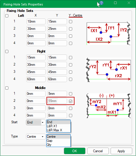
You can specify up to four (4) individual holes with different positions from Right, Left or Middle of flap.
The following example shows the Middle holes Start position is from the End and the spacing Type is Centre - see below for more examples.
Start Position and Spacing Type
The Middle holes drop list allow you to select the Start position of the hole and the Type of spacing.
Start position of middle holes from...
End : Position of holes are calculated starting from the Left and Right End position of the flap.
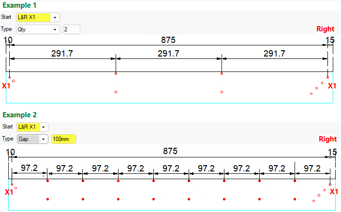
L&R X1: Position of holes are calculated from the first hole positioned from the Left and Right end of the flap.
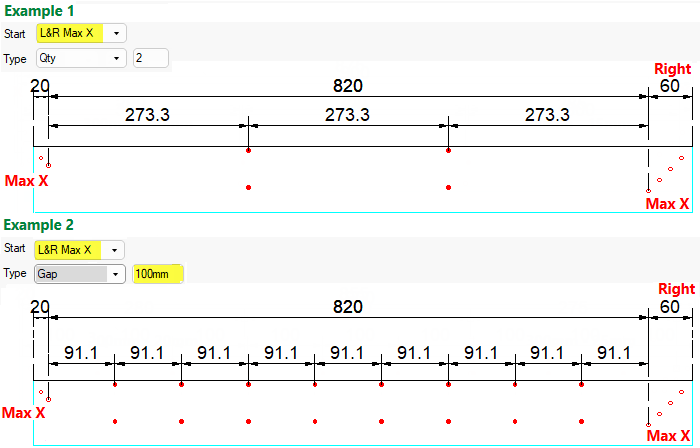
L&R Max X: Position of holes are calculated from the last hole positioned from the Left and Right end of the flap.
Type of spacing of middle holes...
Centre : Middle (single) holes are Centred.
Gap: Middle holes can be placed evenly spaced with a maximum specified Gap width.
Qty: You can specify the quantity of middle holes required and they will be calculated to be evenly spaced.
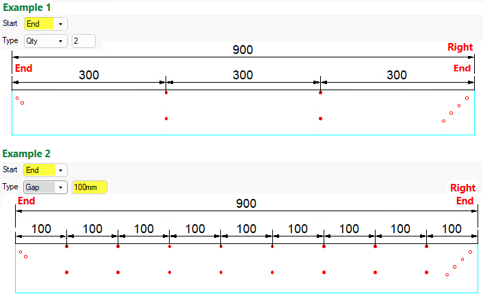
Examples
Start from End Position
In these examples, the holes are calculated starting from the End position and evenly spaced.
L&R X1 : Start from X1 Position
In these examples, the holes are calculated starting from the first hole postioned from either end and evenly spaced.
In example 2, note that the holes are evenly spaced up to the maximum gap specified i.e. 100mm.
LR Max X : Start from Max X Position
In these examples, the holes are calculated starting from the last hole positioned from either end and evenly spaced.
In example 2, note that the holes are evenly spaced up to the maximum gap specified i.e. 100mm.
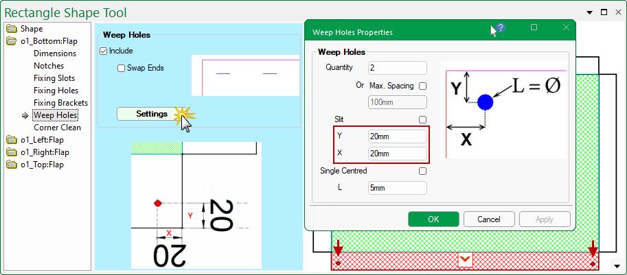
Weep Holes are single line machine steps, either a drill hole or a slit, included in the ‘Flaps’ to allow for draining water behind panel once mounted.
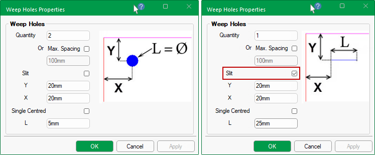
The Quantity of Holes/Slits will also determine the position i.e.
- will position a single hole/slit...
- either Left or Right (use the Swap Ends check box on the Weep Hole page to adjust);
- or enable the Single Centred option for Middle.
- will position the two holes/slits both Left and Right.
- will position the three holes/slits Left, Right and Middle.
- will position the four holes/slits evenly spaced.
The Slit check box determines whether the weep holes are machined as holes or slits.
The L value determines either the length of the Slit (if enabled) or the diameter of the hole.
At Shape level, weep hole parameters are located on the required Flap > Weep Holes page.
In this example, there are two (2) weep holes, one on the Left and one on the Right.
Brackets are available to secure ACM parts when installed. These are fixed with a pair of holes.
The brackets on adjoining parts, however, cannot be in the same position. Their position, therefore, needs to specified for each flap.
These holes can also be added to the Secondary Flap in the same way.
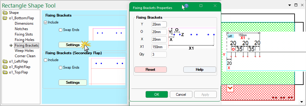
At Shape level, bracket hole parameters are located on the required Flap > Fixing Brackets page.
Bracket holes can be applied to the main and secondary flaps. Simply tick the applicable Include check box and press the Settings button to make changes.
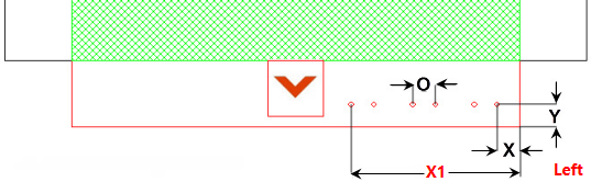
The default placement is to the Left, as shown. Use the Swap Ends to place on the Right.
If you make amendments and wish to reset values back to the properties, press the Reset button.
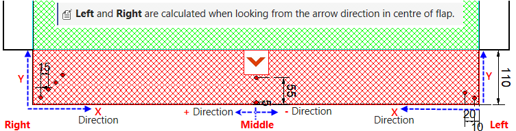
Left and Right are calculated when looking from the arrow direction in the centre of the flap.
The Swap Ends option, on the Fixing Brackets page, switches the start point from one end of the flap to the other.
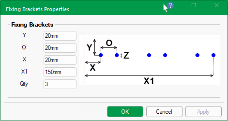
Z : Hole Diameter
Diameter of the hole. The actual diameter of the hole will depend on the tool chosen in .
Y : Distance from Edge
Distance from the outside of flap to all holes.
O : Distance Apart
Distance between holes sets. The example has 3 sets.
X : Distance from First Hole
Distance from edge to first hole.
X1 : Distance from Last Hole
Distance from edge to the last hole.
Qty of Sets
Brackets are made up of sets of holes. In this example, there are 3 sets of holes.
See Also