ShapeMaster User Guide
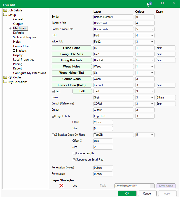
The Setup > Machining page is used to specify the common tooling requirements for the supported machine steps in the Catalog/Drawing Properties.
These options can also be controlled at shape level by using the Machining button on the Shape > Options page.
 click on buttons for a quick link to related topics.
It allows you to set the default Layer names and associated DXF Layer Colour which is represented by a number e.g. 0 = Black.
The DXF layer names required by some nesting/machining systems (e.g. Biesseworks®, EzyNest or EnRoute) are more than just a name. They are a string that defines the required machining strategy, containing information such as the tool to use, whether to route or drill, the depth etc.
The colour used in the DXF is used for visibility within ShapeMaster, not by the machining software. When DXF files are created in the design applications, different types of machining operations are separated onto different layers in the DXF files. The geometry on all the Layers in a file represents a single part, and all the machining such as drilling, milling and cutting, that is to be performed on that part.
The Diameter of the tool used for each of the machine steps. The actual tool size is controlled by the strategy selection in EzyNest and the actual tool fitted to the machine.
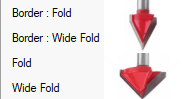
These allow the fold lines (usually machined with a V cutter) to be made as continuous as possible to reduce the number of tool lifts.
Generally the Fold lines fold up to 90deg. The Wide Fold is an alternative fold layer output that folds past 90deg and would usually use a wider V cutter such as 120deg.
So the difference between the Fold and Wide Fold would be the angle of the tool.
Securing holes can be place around the edges of the tabs on shapes. The presence and location of holes can be edited by using buttons provided.
Securing holes can also be edited from the Setup > Holes page. Follow the links for full discussion on...
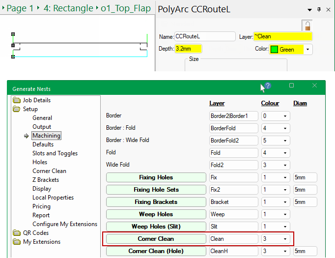
The Corner Clean button allows you to add a continuous (triangular) toolpath into each corner to allow a small tool to get in and clean the corner out.
Example of Machining
The material used in this example is 3mm and the Depth shows the specified Penetration value added to the depth of the tool to be run.
The Corner Clean (Hole) allows you to create a hole on each corner so, in addition to a Layer name, a drill Diameter is required.
The Name property available on each part can be machined onto the part or just displayed in the DXF (by not associating a toolpath to the layer in EzyNest).
Text, if enabled, will also display in the shapes Preview Pane and be displayed on reports such as the Column Report.
Having the Name etc engraved inside the part is useful for future reference if a part gets removed and requires a remake.
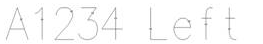
If this is a requirement, please ensure that the Machine Vector Font checkbox is turned ON, forcing ShapeMaster to use a 'single stroke' font called "Hershey", shown, and in the ATP Preferences the DXF Import Option is set to Legacy.
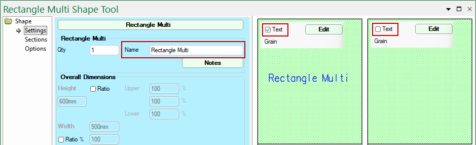
When the Text checkbox is enabled, the Shape Name is displayed by default but can be changed using the Edit button.
In this example, the Colour has been changed from 3 (green) to 5 (blue) for clarity - see also Shape > Settings.
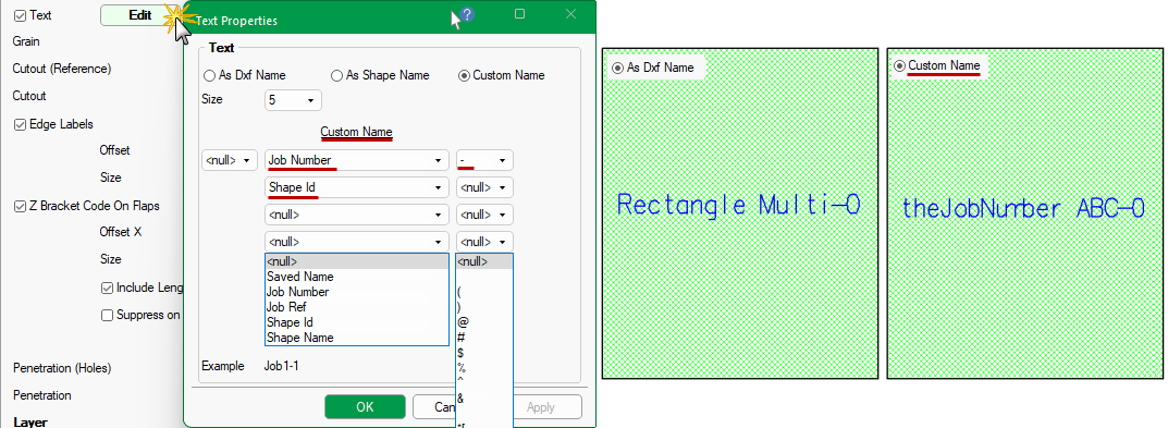
The format of the Text can be further controlled by using the associated Edit button.
The default is As Shape Name (shown below) but you can change/customise this by using the radio buttons.
In this example the Custom Name has been used i.e. Job Number plus a dash (-) plus Shape ID (here it is 0 as we are looking at the Tool)
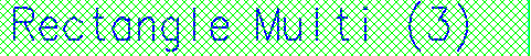
Most fonts will product patterns that require a lot of tool activity to produce, as they have a width to each character, which will mean that the Machine Vector Font checkbox will need to be turned OFF. An example of a multi stroke font, is as shown...
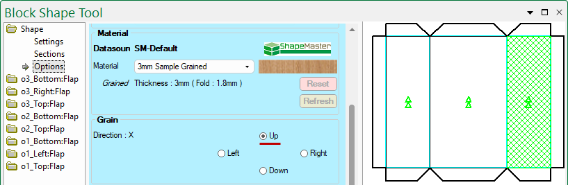
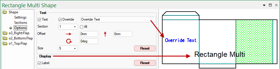
On the Shape > Options page of both Standard and Multi Shapes, this feature can be turned on/off and customised, as shown.
On Multi Shapes, there is also the ability to move text label between sections (or have the text on All Sections).
The Custom codes can be made up of a collection of concatenated properties (evaluated individually for each part), each property delimited by a single character (each of which is individually chosen).
The possible properties that can be selected from the drop list, as shown above, are:
- <null> = Nothing
- Saved/Drawing Name
- Job Number
- Job Reference
- Shape ID
- Shape Name
Example of Custom Code : Shape Name (Shape ID) uses delimiters space and open/close brackets.
Click to view Custom selection
The possible delimiting characters are:
Delimiter Delimiter Delimiter Delimiter Delimiter <null> = Nothing ^ + , [ = Space ? = . ] @ ! _ ( { # < * ) } $ % - \\ &
Each shape has the ability to be nested with the grain in a chosen direction and therefore has a layer name. Set the colour and tool diameter as required.
Whether a material is grained or not is designated in the Material definition - see Setup > General / Materials.
Normally this would not actually be machined but it can be by associating a toolpath to the layer in EzyNest.
The cutout feature allows customers to take existing DXF files of outlines and machine repeated sets of up to five (5) different outlines on any shape.
The Cutout default Layer name and DXF colour can be specified and there is also the layer name for the Reference point (which can be ignored in the actual machining).
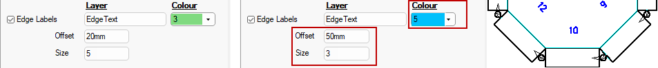
A machinable label can be added to each edge of the body of the shape and therefore requires a Layer name.
By default, the Use Edge Labels checkbox is ticked because if turned off, the text will not be displayed in the preview etc.
The colour, size and offset of the font defaults are set here. In the image (below right) these have been changed to a smaller font in blue.
Z Bracket Code on Flaps - checkbox needs to be ticked if you want to output the Code on Flaps (to be engraved/written);
Layer - DXF layer name e.g. TextZB
Colour - DXF colour of label on flaps. 0-8 can be selected from the drop list i.e. 0=Black, 5=Blue.
Offset X - allows you to specify and offset for the holes away from Centre of adjoining part.
Size - Label text size.
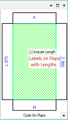
Include Length - Include the length as well as the Code on the flap.
Suppress on Small Flap - Suppress the label if the flap is deemed too small to receive it correctly.
These settings are a repeat of the machining options on the Setup > Z Brackets page.
Example of Code and Length on Flaps
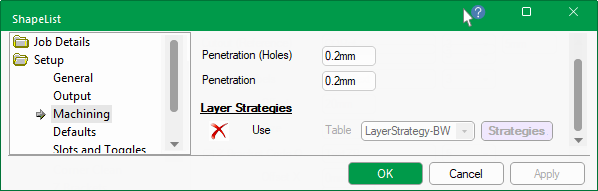
These options control penetration of a "through" machine path. Routing and drilling are controlled separately.
Assuming that the tool will run to the depth of the material thickness of the part, the specified Penetration value will be added to the depth of the tool to be run.

When DXF files are created in the design applications, different types of machining operations are separated onto different layers in the DXF files. The geometry on all the Layers in a file represents a single part, and all the machining such as drilling, milling and cutting, that is to be performed on that part. In order to process the part, the ATP needs to be instructed about what operations, called Strategies, should be applied to each layer of geometry in each DXF file. As a part is processed, this mapping of toolpath strategies to apply toolpaths to each piece of geometry in the part is used.
Layer Strategies can only be launched if the Use option is enabled in the registry settings, which should be edited by advanced users ONLY.
It is strongly advised to contact our CabMaster Support Team to assist you to make the required changes.
The DXF layer names required by some nesting/machining systems (e.g. Biesseworks®) are more than just a name. They are a string that defines the required machining strategy, containing information such as the tool to use, whether to route or drill, the depth etc.
To date CabMaster Software™ has used formulas in the Layers table to define these strategy strings. However, not all layer names are mapped via the Layers table. For example, some come from custom machining tables or are keyed in by the user through the application's machining editor.
To overcome this, the translation into the more complex strategies for all layers now occurs as the application exports the machining DXFs.