ShapeMaster User Guide
In this topic we will be discussing the options for the overall dimension of each section of a shape.
The location page of these options are dependent on the type of shape i.e...
The only differences, as shown here, are...
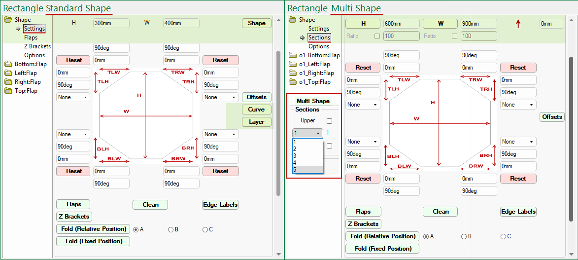
The Height and Width edit boxes can be used to change the dimensions of the selected shape, however, Multi Shapes are dependent on defaults on the Settings page (click image to view).
Ability to base section height and/or width on an overall size and ratio percentages.
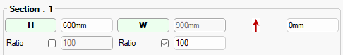
Sections page options - Click to view default setting on Settings page
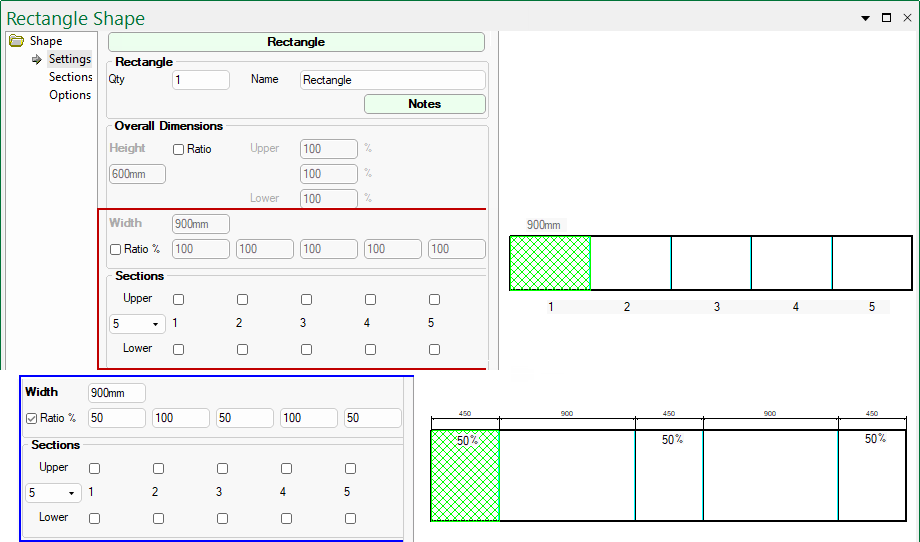
The Ratio check and edit boxes are greyed out by default (compare to top right image) and can only be made available by enabling the Ratio checkboxes on the Settings page (click on above image to view). You can see that, on the Sections page options shown above, when the Ratio checkbox is left unticked, the Height edit box is made available and visa versa e.g. ticked for Width, which now cannot be amended.
Example of Ratio % and use
In the first example, the Width Ratio % is disabled on the Settings page and each of the 5 sections are 900mm wide.
The second example has the Width Ratio % enabled and Sections 1, 3 and 5 are set to 50% which is 900/2 = 450mm. The Width can also be changed.
Reset buttons
The
and
buttons can be used to reset to the overall shape height, taking into account the ratio default.
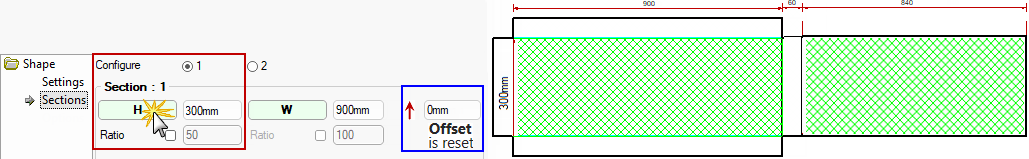
The H button also resets the Section Offset back to the default (in this case 0mm).
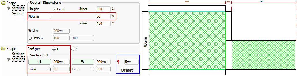
Example of using H button to reset
In this example, we have enabled the Ratio checkbox on the Settings page and set the Height to 50% but as you can see this has only applied to Section 2.
The Sections page shows the correct defaults applied but Section 1 is still 600mm high. An Offset of 5mm has also been applied.
If we now press the H button, the height will adjust to 300mm (same as if the Ratio checkbox is ticked) and the Offset is reset - see example discussed below.
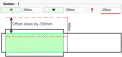
Example of Offset button
In this example, we have Offset the shape by 250mm in the negative direction (i.e. down).
Each corner of the shape can be individually controlled.
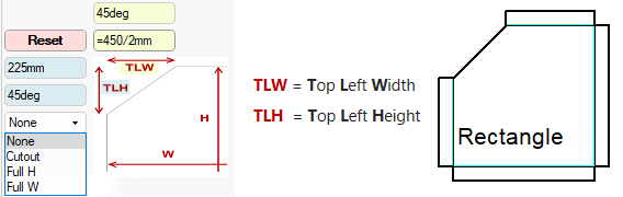
As well as text (e.g. 225), edit boxes can be formula controlled i.e. typing in =450/2 (as shown highlighted in yellow) will provide a result of 225.
When both lengths have been input the Angle will automatically update.
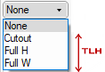
The Cutout drop list is used to define the selected section of a shape as a cutout.
Selecting Full H will cutout the shape section using the full height of the shape, after the width is entered.
The Angles are automatically calculated. In this example, these have been confirmed using the Angular Dimensioning tool.
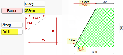
Click to Expand
Selecting Full W will cutout the shape section using the full width of the shape, after the height is entered.
The Angles are automatically calculated. In this example, these have been confirmed using the Angular Dimensioning tool.
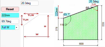
Click to Expand
Selecting Cutout will cutout the shape section after the height and width is entered. The Angles are automatically calculated.
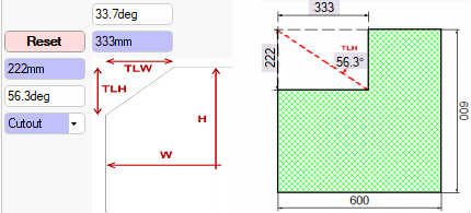
Click to Expand
The Fold options shown here are only available for Sections 2 to 5, if available, on Multi Shapes.
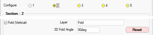
If changes are made, use the Reset button if you what to re-apply the Drawing Properties.
The Layer name is designated on the Setup > Machining page - see Folds.
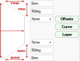
The Offsets button is available for both the Standard Shape and Multi Shapes.
The Curve and Layer buttons are only available with a Standard Shape.
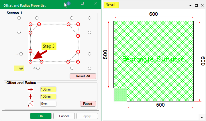
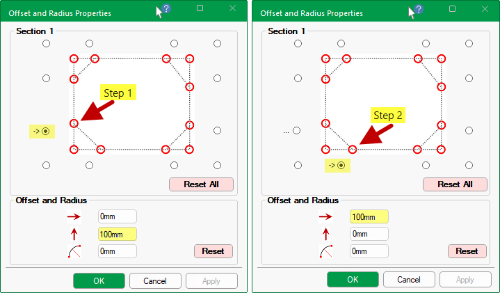
The offset moves the points around. To illustrate, we will Offset the bottom left corner of a Rectangle Standard 600mm x 600mm shape.
Press the Offsets button (shown above) to open the Properties dialog and...
 100mm and click Apply.
 100mm and click Apply.
100mm and offset 100mm and click Apply.The preview will update to show the result i.e. the cutout to the bottom left corner. Note that dimensions were added for clarity.
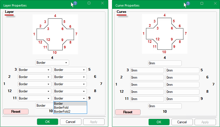
Provides the ability to select different layers for the sides on the main shape (not flaps).
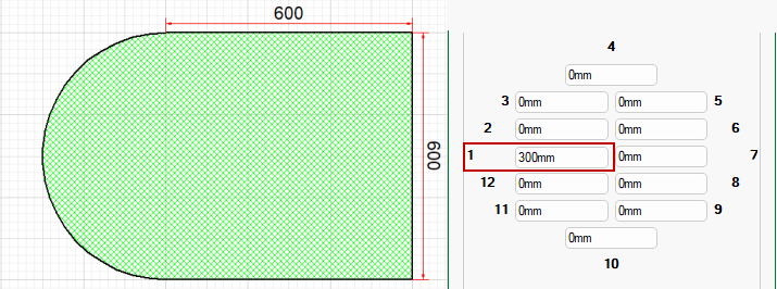
The dimensions entered for curves are RADII i.e. the radius of the curve from one point to another (the points being the corners of the shape) - the centre will obviously vary depending on the value.
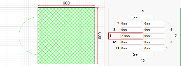
Example 1: If the Radius is the half length of the line then the centre will be the centre of the line and the curve will be a semicircle.
Example 2: If the radius is less than half the line length then the application centres it on the middle of the line anyway and creates an unjoined lump - which may cause errors when exported to be cut.
Click to view Machining Issue
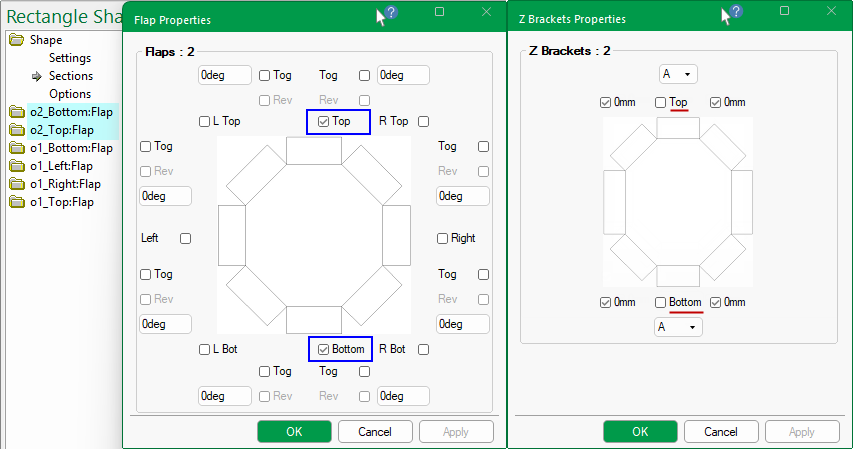
Z Brackets Properties that are dependent on Flaps being present. The options available are the same for Standard and Multi Shapes.
The difference is in where the options are located i.e. pressing the  and
and  buttons for...
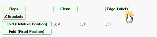
The Clean button  options are useful when a corner cutout is applied. It allows you to clean selected corners of each available Section of the shape.
The following illustrates how you can clean a selected corner (e.g. bottom right) but this clean is not applied to other corners (e.g. top right) unless the Include checkbox is enabled to apply the clean. The Reset All will change all corner options back to the Drawing level.
The diagram and available radio buttons for selection are based on the shape of the selected section - click on image to view examples.
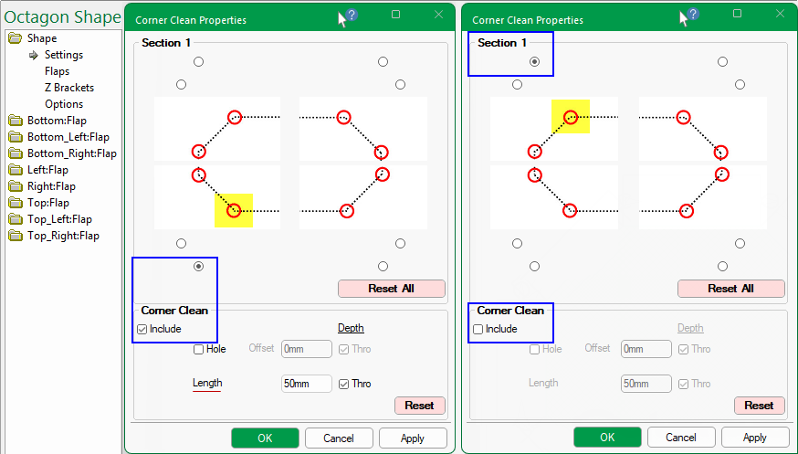
Click to view more examples of Sections and their shape options
Ability to add a machinable label to each edge of the body of the shape.
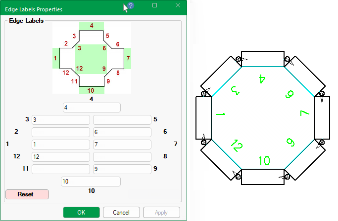
By default, the Use Edge Labels checkbox in the Drawing Properties is ticked, as shown. If turned off, the text will not be displayed in the preview etc.
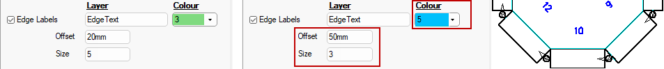
As it is machinable, a layer name is required. The colour, size and offset of the font can also be controlled in the Drawing Properties.
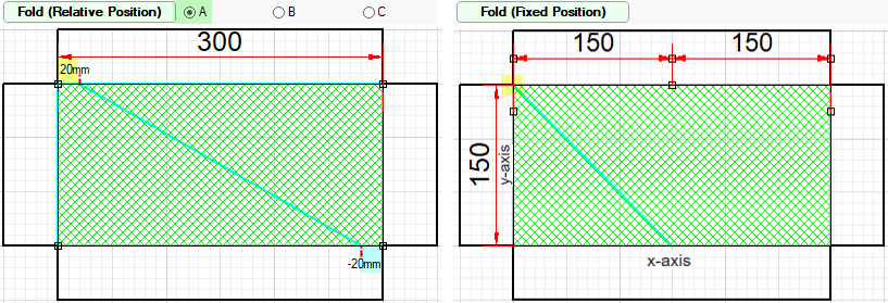
The Fold buttons open anExtra Fold Properties dialog which allows you to include manual fold lines to either a Relative or Fixed Position. by pressing the applicable button, as shown below.
Then simply tick the Include checkbox to turn on this feature and...
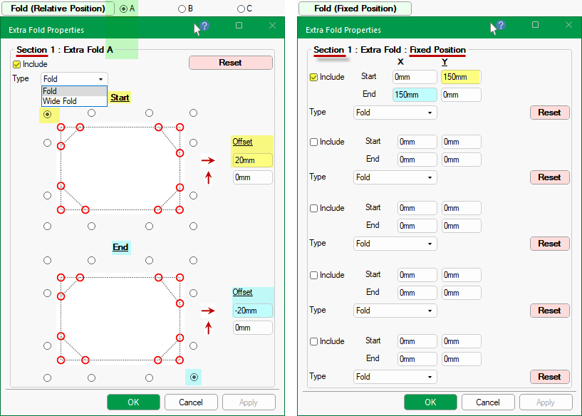
Include up to manual fold lines to the main shape, using the radio buttons to designate start and end positions.
An Offset can also be specified - see example below left.
Include up to five (5) manual fold lines at a fixed position per section of part.
Simply tick the Include checkbox to add a line from Start point X & Y to End point X & Y on each part.
Example