ShapeMaster User Guide
Drawing tools are just like a staging area where items are prepared for addition to a drawing and can be customised before or after placement in the same ways as shapes.
For many tools you can also create/save customised tools, a QTD file in the appropriate subfolder of ToolData, which can be selected/loaded when required. The exception to this are Cutout Tools located on the Machining Editor, which can only be customised but not saved for future use.
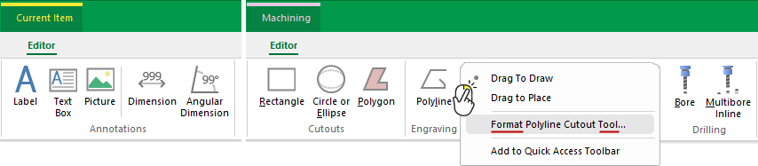 |
When you right click on any of the above drawing tools, you will be presented with menu commands similar to the example.
To locate information on any of the Drawing Tools above, ![]() click on the area of interest.
click on the area of interest.
 Watch the Video tutorial on creating a customised drawing tool.
Items/objects such as text labels, rectangles, dimensions etc, have their own properties in the same way as shapes. Tool properties are saved in the appropriate subfolder of the ToolData folder with a QTD file extension (see Location notes).
All drawing tools have what is known as the default tool that is usually saved in a state where the settings are as desired, so that you don't have to make changes every time you use it. However, note that if you make changes to the currently selected tool or select a custom tool, these new settings will be saved upon exit of the software i.e. new settings become the default. Because the default tool acts as a template for creating new objects, any changes to these settings will be saved upon exit of the software.
Of course, the item/object can be changed further after placement, in the same way as a shape, without affecting the default tool or you can create a custom tool which you can save for future use.
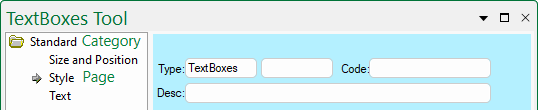
Property Sheets are presented as Category trees with Category folders and Pages that contain property sheet options. Note that the Category tree is only available if there is more than one category or page and is used to change between the different groups, categories and its' pages.
The Type box is used for describing which class of item the object is. Optional fields include the (1) subtype (i.e. extra field alongside type) and is just a qualifier that can be used, (2) Code text box is for the name of the particular object, (3) Description text box is for a more explanatory name for the object.
Click to view Property Sheet without a Category tree.
The close
button (in the upper right corner) closes that property sheet and any changes you make to a property sheet take effect immediately. It does not cancel or rollback the changes you made in any way, it just makes the property sheet invisible until you open it again.
Extra Notes
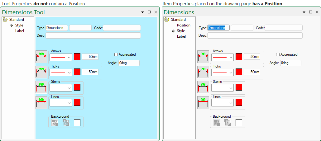
The Properties Sheet of a Tool and a drawing object are very similar except for the following differences:-
- The Tool properties do not contain a Position, since they do not exist on the drawing page yet.
- The Tool properties have blue background and a placed Object has a light grey background.
- This was done to remind you that you are viewing the properties of the default tool, not a particular drawing object.
- The title bar includes the word Tool in description.
- This is also to remind you that the tool is being edited.
Differences between Tool and placed Object
When placed on a drawing, the item/object is created as a copy of the default tool and has a light grey background. This means you can customise the settings such as font and colour etc, before placement of the item/object on the page and no further changes will be required. The benefit of this is that you can place several similar items/objects without modifying them all individually i.e. the default tool acts as a template for creating new objects.
For many tools you can create customised tools and save for future use. Customised tools are saved in applicable subfolder of the ToolData folder.
File Locations for use with your ShapeMaster product can be viewed by accessing the File > Options [F10] dialog.
Quick Access to Saved ToolData
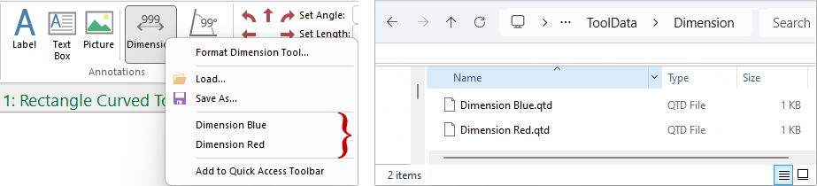
Customised tools saved in the ToolData folder are available from a quick access list as shown below left. However, note that only the first 10 are shown in the list (in alphabetical order). To use those not in the list, you will need to use the Load command.
Click to view example of over 25 files
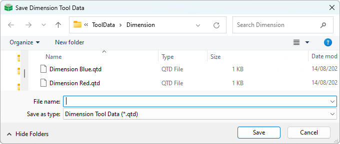
When you have completed customising a Tool, right click on the applicable Tool button in the ribbon and save as with a descriptive new name in the appropriate subfolder of ToolData folder. The file type will be QTD file.
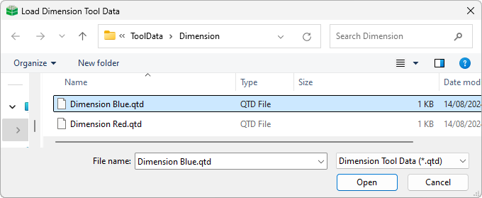
The Load command is really only required when the list is greater than 10 saved files.
When you select the 'Load' option the following dialog is presented, open at the applicable folder under ToolData. Simply select the required QTD file.
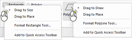
Tools such as Text, Picture and Shapes can be selected and then you can choose to...
If you are drawing a 2D shape, such as a rectangle, you can click for one corner and drag to change the size, releasing the mouse at final size.
If you are drawing a line, such as a PolyLine (i.e. not a 2D shape), then instead of calling the first option Drag to Size it is called Drag to Draw.
Alternatively, the size can be specified in the format tool and then when you drag, a rectangle of that fixed size will move around.
This video discusses how to save time by creating customised tools and setting standard defaults. [5:11 mins]