ShapeMaster User Guide
The Movement group of commands are located on the Current Item Editor and Machining Editor tabs.
Use this group of commands for accurate setting and drawing.
 |
To locate information about any part of image above,  click on the area of interest.
By default, movement is "one way" in a clockwise direction and formulas can be entered directly into edit boxes i.e.
 which provides the same result as using the calculator available on the Current Item Editor.
To use the Movement Toolbar :
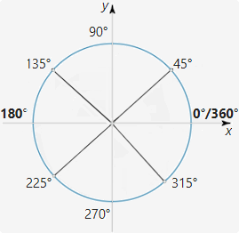
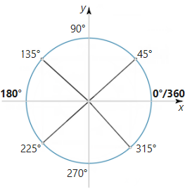
The standard angular convention is used, having zero degrees to the right, increasing in an anticlockwise direction as shown.
Note that adding or subtracting 360 degrees from an angle has no effect, so if you wanted to specify a distance down to the right at 30° you could either specify an angle of 330° or -30°.
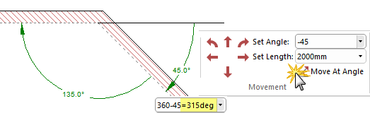
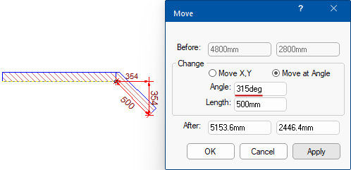
In this example, using the compass setting an angle of 315° will provide an angle -45° (even though the internal angle is 135°).
Alternatively, holding down the [Shift] key as you drag the mouse, constrains the movement direction, e.g. when drawing a wall, it not only ensures a straight wall at 0° but also allows you to draw the wall at the nearest 45° angle. You can also use the Precise Movement Input dialog (discussed below) by pressing the keyboard dot
while dragging a point/handle.
Clicking on the applicable arrow command moves the mouse cursor in the selected direction by the distance specified in the Set Length box. This has the same effect as positioning the mouse at the object you placed last, moving it by an exact distance in a certain direction and then clicking the mouse button.
When you have a drawing tool available in Editor mode, an object will be placed at the destination point. These commands combined with the others on the Movement menu provide a simple and accurate method of placing objects such as cutouts.
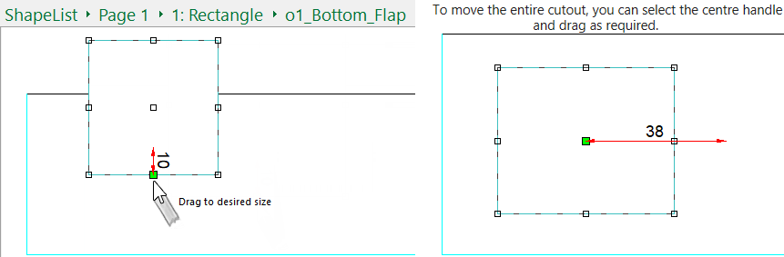
You can also move or increase/decrease the size of a selected item by simply selecting a handle and dragging.
Example
Clicking on the applicable arrow command moves the mouse cursor along at a right angle from the angle specified in the Set Angle box.
These commands have the same effect as adding 90° (for Turn Left) or subtracting 90° (for Turn Right) from the current value of Set Angle and then using the Move at Angle command.
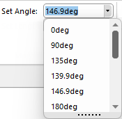 This edit box allows you to enter an angle value for use with the Move (Arrows) and Angle commands. Angles can be typed directly into the text box, or previously used values can be selected from the drop down. See note above on standard angular convention.
Another edit box similar to the 'Set Angle' control, except the value entered here is the distance used with the Move (Arrows), Angle, and Turn commands.
The Length can be expressed as a measurement or formula i.e.
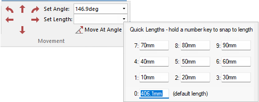
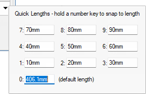
You can set 10 commonly used lengths as standards for quick use by clicking on the down arrow, as shown right. These lengths can be used wherever a length can be input, such as walls, chamfers, offsets etc. You can also use complete formulas instead of simple numbers.
To use a Quick Length, hold down the corresponding number while holding down the mouse button. For example, to draw a line that is 200mm long, hold the corresponding number button to that Quick Length ("0" or zero in image) while drawing and it will automatically draw the line 200mm long. When completed, release the mouse button.
Troubleshooting - Shape movement is locked to a set value
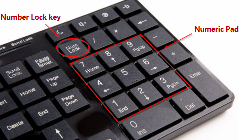
Solution: Hold down the relevant Quick Length number key on your keyboards numeric pad and then also press the Number Lock key.
In this example, the shape is stuck only allowing 50mm movement. As per the Quick Length dialog above, this corresponds with the numeric key '5'.
To free this, hold down the 5 key on the number pad, then press the 'Num Lock' key (while still holding down the numeric key).
 Watch the Video on using the Quick Lengths tool and Precision keyboard dot to Chamfer/Fillet a Corners.
Moves the mouse cursor by the distance specified in the Set Length box at the angle specified in the Set Angle box. This is similar to the Move (Arrows) commands, except the direction can be set to any angle instead of being restricted to horizontal and vertical movement.
As with the Move commands, Angle has the effect of moving the mouse from its previous position and then clicking the button at the destination point.
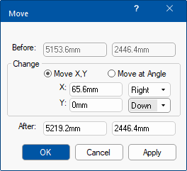
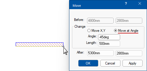
The precise movement input dialog is another way to move points - see also topic on Measurement and Placement.
Simply start dragging your selection and at the same time, press the keyboard dot once and let go.
This will open the dialog where you can either Move by X,Y coordinates Left/Right/Up/Down or Move at Angle.
In the following example, we will add a section of wall at a Length of 500mm at an Angle of -45deg.
This feature in ShapeMaster is available on the Current Item 2D Editor.
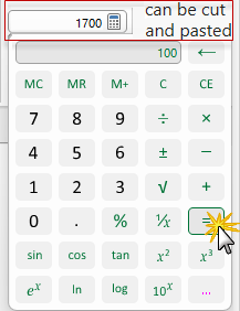
You can type directly in the edit box or click on the  to open the calculator application, as shown. When the equal sign is clicked, the result is displayed in the edit box e.g. 1700. The result can be cut and pasted between the calculator and text boxes in ShapeMaster, so you do not need to write down results and type them back in. It a handy tool and takes up next to no space.
Pressing the  button will open the Standard Windows calculator.
If you use this command and nothing happens, it most likely means that you do not have the calculator installed.
Formulas can also be entered directly into edit boxes as shown here.