ShapeMaster User Guide
The Machining Editor allows you to easily edit the machining of each part of a selected shape.
Features include:-
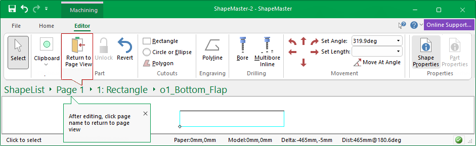
To select a Machine part and access the Machining Editor, use the Breadcrumbs Bar. In this example, we selected the Bottom_Flap part of the shape.
To return to the List, either use the 'Return to Page View' command or click on the 'Page' reference in the Breadcrumbs Bar.
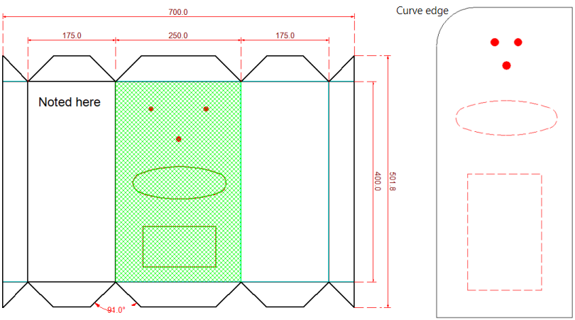
Allows you to edit the existing shape (per section). You can add Curve edge , a rectangle, circle, drill hole or gang of drill holes and more.
Machining can be added/edited as required - follow the following links for discussion on...
In this example, dimensions and text were added to a Block shape and then cutouts etc applied!
When in the Current Editor mode, dimensions (horizontal, vertical and angular) were added to the part, as well as text labels and text boxes to the current part. These details will be included in reports that display images. E.G. ShapeList reports.
In Machining Editor mode, drill holes and cutouts have been added to Section 2 of the Block shape using the Ribbon Commands.
The right click menus provide more commands e.g. Curve Edge/Add Corner and a Grid can be turned on to help with positioning - click on image to view.
Click to view Machining Editor mode
 When you first select machining, or a formula controlled item, it will need to be unlocked.
For detailed discussions on the above, follow the links provided.
The part will be opened for editing in the Main window, as shown.
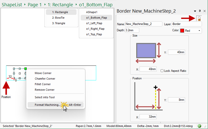
In the following example, we have placed a Rectangle Cutout on the Bottom_Flap and used the right-click menu to Format Machining which opens the Property Inspector (docked) for the placed cutout.
The Property Inspector shows that the Size of the currently placed rectangle is 48mm x 40mm. The Position is measured from the left hand bottom corner. You can manually change both the size and the position by using the edit boxes, as required.
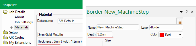
Ensure that the Depth of your cutout corresponds to the material thickness plus penetration (set on the Setup > Machining page of the Drawing Properties.
For example, if the material is 3mm thick, the cutout must be 3mm (material) + 0.2mm (penetration) to ensure a successful cutout.
You can create a Duplicate of the placed item by using the right-click menu option or use Keyboard Shortcut Ctrl+D.
 dot once and let go.
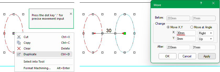
Alternatively, you can use the Select Into Tool option...
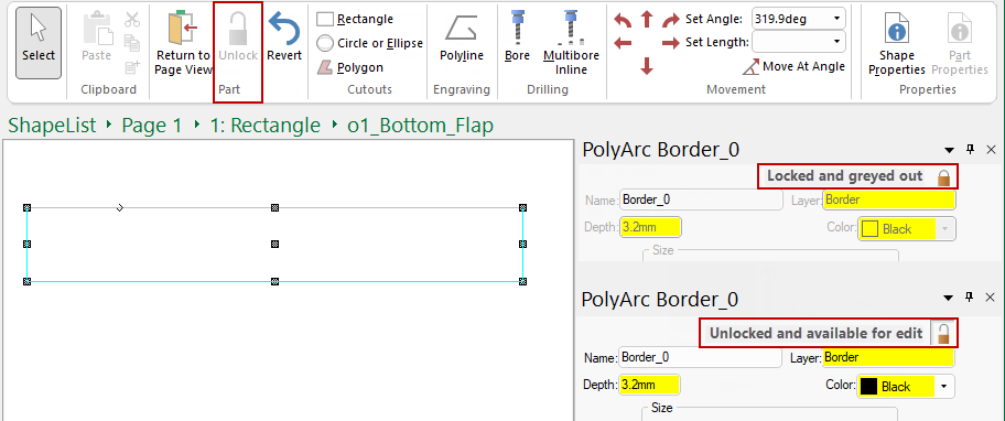
To ensure you do not accidentally modify the machining of a part, all parts are locked until specifically requested to unlock before editing can take place.
This is very simply done by clicking the padlock ![]() command button. This will allow you to add or modify machining that is not currently formula controlled. To relock the part, use the 'Revert' command button.
command button. This will allow you to add or modify machining that is not currently formula controlled. To relock the part, use the 'Revert' command button.
Items that are formula controlled, such as the depth of existing holes, layers names and display colours can also be unlocked by clicking on the padlock button located within the MachineStep editor, as shown. This will remove the parametric formula in the background and let you override with your new requirements.