ShapeMaster User Guide
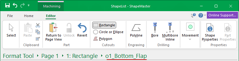
The Machining Editor provides commands for adding new machining and is accessible when you select a shape/item part for machining using the Breadcrumbs Bar.
 Watch the Video for a brief overview of how you can design custom parts.
Before you can use the Editor facility, you first need to click on the Unlock command button.
The Cutouts group includes tools for creating Rectangle, Circle/Ellipse and Polygon cutouts.
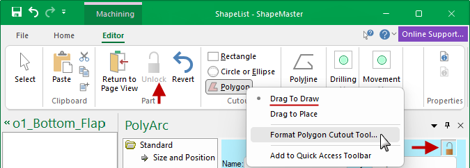
The options on the right click menu allows you to customise the selected tool and provides drag options for placement.
To ensure against accidental changes, the Part needs to be Unlocked and then, when you Format the required Cutout Tool, you need to Unlocked the Property Sheet before you can manually enter values for Size etc. and check the Depth of the cutout.
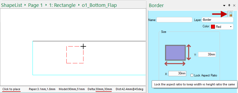
Some tools have 'Drag' options, as shown in the example above. If not, simply 'Click to Place' - as per instructions in the Notifications area of the Status bar.
In the following example, the Rectangle Tool has been enabled with 'Drag to Place' and unlocked. The Size has been set to create a 30mm x 30mm square and then, as per the notification, 'Click to place' as required.
Drag Options
Drag to Size
If you are drawing a 2D shape, such as a rectangle, you can click for one corner and drag to change the size, releasing the mouse at final size.
Drag to Draw
If you are drawing a line, such as a PolyLine (i.e. not a 2D shape), then instead of calling the first option Drag to Size it is called Drag to Draw.
Drag to Place
Alternatively, the size can be specified in the format tool and then when you drag, a rectangle of that fixed size will move around.
The best way to position a cutout is by simply enabling the tool and 'click to draw' by dragging the cutout.
If you want a precise position, start dragging your selection and at the same time, press the keyboard
dot once and let go to open the Precise Movement Input dialog.
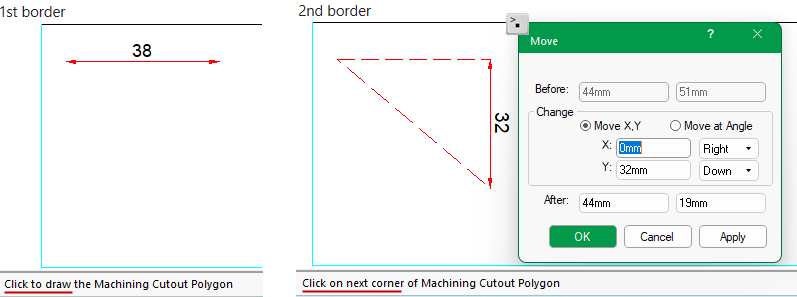
Example
In this example, we first enabled the Polygon tool and used 'Drag to Draw' the cutout to create the 1st border line (the temporary dimension is automatically provided while drawing i.e. 38mm). Then used the Precise Movement Input dialog to created the 2nd border line of the polygon by changing the Move Y by 32mm.
Simply start dragging your selection and at the same time, press the keyboard
Formulas can be used in the edit boxes to calculate the required distance for movement or simply type it, then...
- click Apply to see the change, as this allows you to Cancel the change.
- click OK when you are satisfied.
Insert a freehand line into a drawing in the same manner as the Polygons tool. The only difference is that it does not have to form a closed shape, being just a series of joined straight lines i.e. each click on the screen adds a vertex to the line.
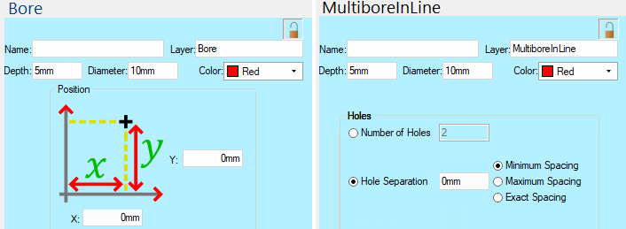
The Bore tool is used for Single Drill Holes. This tool gives you the option for the X and Y Position of the single hole, the depth, diameter, layer name and display color.
The Multibore Tool is used for creating a 'Gang of Drill Holes'. This tool has the same options as the Bore Tool but also adds options for the start and end points of the gang of holes. The Hole options allow you to ...
or
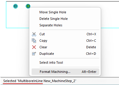
When part editing, the notifications area on the status bar will describe the selection. In the following example, the MultiBore drill hole.
Click to select and, if the Machining Property Sheet isn't already open, use the right click menu to Format Machining...
To edit a part you will first need to Unlock and enable the "Select" tool.
As the mouse moves closer to a shape part or item (including holes), it snaps/jumps to the closest handle.
This video is a brief overview of what you can achieve using the Part Machining Editor (3:38 mins)