In This Topic
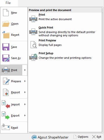
To locate information about any command  click on the area of interest on menu image above.
Main menu headings are collapsible - click to hide/show.
Keyboard Shortcut: Ctrl+N
Creates a new drawing based on the current library. If the current drawing has been modified since it was last saved, you will be prompted to Save the drawing first. You can open an existing drawing with the Open command.
Keyboard Shortcut: Ctrl+O
Loads an existing drawing via the Open dialog. It first closes the current drawing in the same manner as the New command, by prompting you to save any changes.
Revert allows you to reload the current drawing from the last saved point.
This command is useful when you add or move shapes around to see how it looks. If you are not happy with the changes you simply select Revert from the File menu. The drawing will then revert to how it was the last time you saved it to file.
Be Careful: If you create a drawing and have not saved it, and then select the Revert option, it is like creating a new drawing and you could lose everything.
Keyboard Shortcut: Ctrl+S
Saves the drawing to its current filename and folder. If saving a drawing for the first time or if changing the name or location of an existing drawing before you save it, choose the Save As command.
All drawings now automatically get compressed when saving. This reduces the size of drawings saved on your computer, therefore allowing for more drawings to be saved and reducing required size of total backups.
Saves the current drawing with a new name by displaying the Save As dialog. You can also change the location of the saved drawing on disk. To save a drawing using its existing name and location, use the Save command instead.
Creates a new email and
includes the current drawing as an attachment. Using this requires that you have an email program installed and configured. The 'Email' command is useful when a support technician asks you to send them a certain drawing.
Displays the Help
About dialog which shows the program name and application version, details of registered company, hardware lock number and sequence number of update applied, days left for expiry if applicable, as well as copyright and system information.
Keyboard Shortcut: F10
Displays the
File Options dialog, where you can change various settings such as the default units of measurement, whether to use 3D acceleration, and an autosave time for your drawings. This area can also be accessed by using the
keyboard shortcut F10. Options include an AutoSave feature which is initiated at specified time intervals as long as the drawing has been manually saved at least once. This area also allows you to customise images and view where your software product is located on your computer. Displays the
File Locations dialog, where you can specify paths to the different , which has several benefits.
Keyboard Shortcut: Alt+F4
Ends the current session. If you have made any changes to the drawing, you will be prompted to save it before the program closes. If you exit without saving your drawing, all the work that was done to it since it was last saved will be lost.
Keyboard Shortcut: Ctrl+P
Prints the current document. If the Print command is selected from the File menu, a Print dialog will be displayed, where you can specify the range of pages to be printed, the number of copies, the destination printer, and other printer setup options. If you are printing a 3D image (in 3D View) then another dialog appears allowing you to adjust the Print Position.
 Watch the Video
 (1:02 mins) on how to print a page range i.e. multiple pages.
Click to Expand
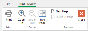
Displays the current drawing as it would appear when printed. When you choose this command, the main window will be replaced with a print preview window in which one or two pages will be displayed in their printed format. The print preview toolbar offers you options to view either one or two pages at a time, move back and forth through the pages of the drawing, zoom in and out, or Print the drawing. Click the 'Close' button to exit the print preview and return to the main drawing view.
Displays the Print Setup dialog, where you can change printer settings such as which printer to use, the page size and orientation.
If your reports and/or labels are printing at the wrong size then check the Paper selection and Orientation.
Click here to view menu and use quick links
To locate information about any
command click on the area of interest on menu image below.
This feature is not applicable for use with .
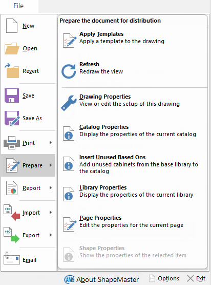
Keyboard Shortcut: F5
Refreshes the window by redrawing the page and optionally recalculates the formulae within all visible items, and all the sections they may import. When using a number of items which have multiple imports, having everything rebuilt may take a while so only use this option when necessary.
Keyboard Shortcut: F4
This opens a dialog which lets you edit properties of the drawing. See topic on Catalog/Library Properties for more details.
This opens a dialog which lets you edit properties of the current catalog. See topic on Catalog/Library Properties for more details.
Adds unused Shape from base library to catalog. This will enable all designer software users to be able to update their library with any new shapes that has added to our Base library without the need to access the .
See Video [0:45 mins] on
how to add
unused Based Ons in both the
and from the
File menu.
Requires Developer Software : Only Middleware developers edit the library properties. These are overwritten with properties and together they initialise properties for a new drawing.
Keyboard Shortcut: F3
This feature is not applicable for use with and the corresponding ribbon command is turned off by default.
Keyboard Shortcut: Ctrl+R
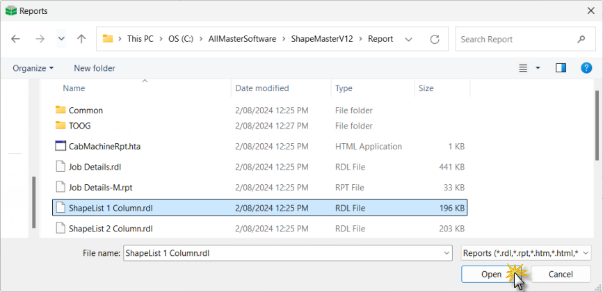
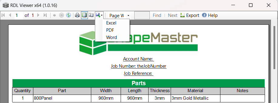
Opens a dialog which lists all the available reports that you can create, such as invoices, cutting lists and door reports. Select one of these reports and click 'Open' to generate it on the current drawing.
Example of Reports dialog
Select the required report (normally sorted under relevant folders) and click 'Open'. Alternatively, simply double click on file name to generate.
Once generated, you also have the option to export this to Excel, PDF or Word format - Watch the Video [1:37 mins].
Video
Exporting Reports to Word (1:37 mins)
Explorer integration is available to view thumbnail images of a drawing directly in Windows File Explorer. Little images are actually created of each page of a drawing and, when a drawing is saved, it carries these images along with the "real" information. To take advantage of this feature, drawings just need to be opened and resaved. Batch resave allows you to more easily do this for collections of drawing files that you may have.
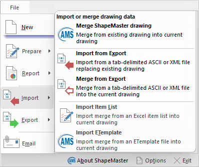
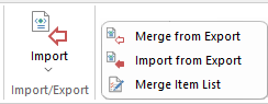
File > Import - Click to view menu
Displays a dialog which is very similar to the 'Create from template' dialog when you first open a drawing. This allows you to select an existing drawing file to merge with the current one or import an earlier version drawing. This is done in the same way that templates are applied to a drawing, so like templates it allows you to control what happens when answers in the current drawing conflict with those in the drawing being merged in.
Loads/imports data from an ASCII (text) or XML file into the current drawing. It will clear all values from the drawing properties and use the ones from the specified file - see also Merge from Export.
Developer Software Users: To export values to an ASCII file, use Minimal Drawing Export or Full Drawing Export - discussed below.
Commands also available in the Library Catalog Manager - see Import / Export.
Loads/imports data from an ASCII (text) or XML file into the current drawing. It will add values from the text file to the ones that already exist in the drawing properties. If a value already exists in the drawing, you will be asked whether to overwrite it or leave the existing value. See also Import from Export above.
Developer Software Users : To export values to an ASCII file, use Minimal Drawing Export or Full Drawing Export - discussed below.
When opening a drawing, if there is file called AutoMerge.tab in the same folder, you will be prompted to automatically merge this file into the drawing as it opens. This is very useful when archived drawings require some changes before being used with your latest library, for example.
Displays a dialog which is very similar to the Open dialog, where you can select an existing drawing file to merge with the current one. This is done in the same way that templates are applied to a drawing, so like templates it allows you to control what happens when answers in the current drawing conflict with those in the drawing being merged in. Refer to Tutorial on Import Item List.
eTemplates Laser room scanner can now produce their output file that can be imported directly into and can include cutouts.
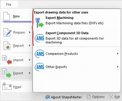
File > Export menu - Click to view
Keyboard Shortcut: F8
This command is available only within Machine software and creates a collection of machining files, for example a DXF format etc. These files contain machining information for each component in the current drawing which is configured to output machining data. This command is also available on the Machining Current and Machining Combined ribbon tabs.
Creates a custom export file with 3D component data, which can be used by certain machining interface software.
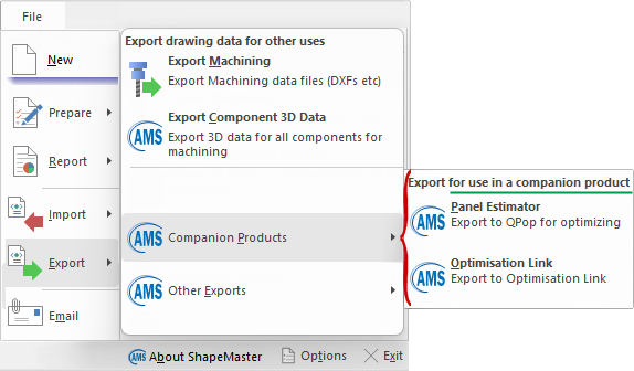
Companion Products
File > Export > Companion Products - Click to view menu
Allows drawing information to be exchanged with the Panel Estimator if it is installed.
Panel Estimator allows you to produce efficient cutting or pressing patterns, it can tell you the best way to arrange boards to produce the most optimal patterns with the least amount of wastage. It is not tied to a particular brand of saw, it will just as easily optimise for a bench saw, laminate press or manual cutting. This allows simple optimisation of cutting lists because all the required shape and section data is automatically transferred.
Allows drawing information to be exchanged with the Optimisation Link if it is installed.
Optimisation Link allows you to interface panels from your job through to a third party saw optimiser. It is an interface for sending data to a panel optimiser i.e. OptiLink is not an optimiser, it is the link to panel optimisers. It supports most formats for sending data to beam saw optimisers.
Optimisation Link allows you to :-
- filter and interface panels from your ShapeMaster job through to the saw optimiser provided by the beam saw manufacturer, or possibly by a third party.
- select which materials to interface and which folder to place your interface files into, thereby providing filtering (for example by Materials) when sending current job data to OptiLink.
There is also a generic format which can be user configured for special optimiser formats.
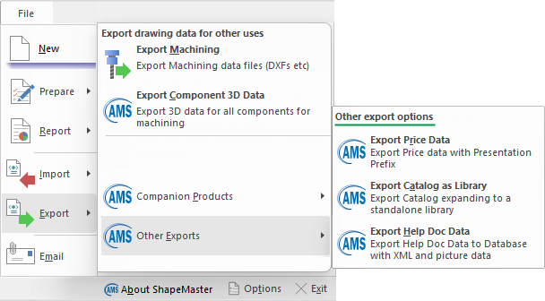
Other Exports
File > Export > Other Exports - Click to view menu
Exports pricing information from each shape in a drawing to an ASCII merge file, using the presentation pricing prefix. This data can then be passed to the Automation Server to generate presentation pricing lists for the shapes in a library or drawing.
Exports catalog expanding to a standalone library.
Exports Help document data to a database with XML and picture data.