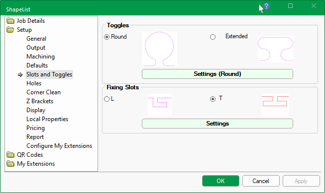
Toggles can be placed around the ends of each tabs. There are two (2) toggle shapes i.e. Round and Extended.
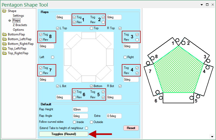
At Shape level, toggle parameters are located on the Shape > Flaps page.
On the Shape > Flaps page, you can use the...
-
Toggles button at the bottom to overrides the dimensions set in the Drawing Properties.
- The style, as indicated on the button i.e. Round, cannot be changed here.
- Tog checkbox to turn On/Off the applicable Toggle. (See numbered checkboxes relating to preview pane image).
- Rev checkbox to reverse the Toggle and the toggle hole on the selected tab.
- Reset button will reset the values in the Default group to the Setup > Defaults page of the Drawing Properties i.e. has not affect on toggles.
Round
Use the radio button to select the toggle shape and then press the Settings button to open the relevant property inspector.
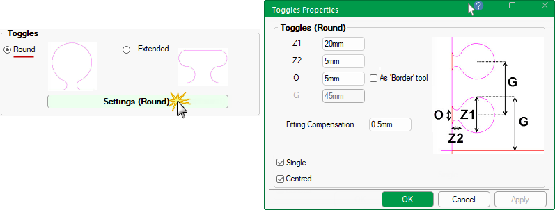
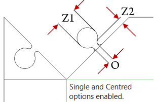
Z1 and Z2 dimensions
These allow you to control the diameter and length of toggles.
Z1 - Diameter of the main part of the toggle.
Z2 - Diameter of the ‘neck’ of the toggle.
O : Opening at Neck
The O value is the width of the opening at the neck of the toggle.
As Border tool option bases the neck of the Toggle on the Border tool diameter.
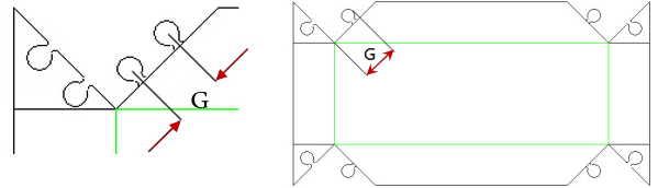
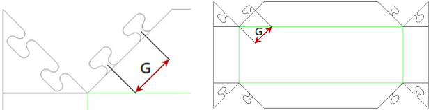
G : Gap Between
This both the gap between the centres of multiple toggles and the gap from the start of the tab to the end of the first toggle.
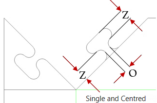
Single Toggle Only
The check box allows you to designate whether a single toggle is required on each tab rather than multiples.
Using multiples will automatically calculate the quantity, and space them according to the spacing between the centres of the toggles, specified as G i.e. ‘Gap Between’.
Centred
Ticking this check box centre's the single toggle on the edge of the tab.
Fitting Compensation
This is the clearance between inner and outer toggle parts i.e. Flap and Tab.
Rather than the toggle and its hole being the same size, this will adjust the sizes to make one smaller than the other.
Extended
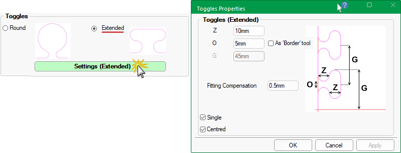
Z Diameter
The Z diameter is the same for the main and 'neck' of the toggle.
O : Opening at Neck
The O value is the width of the opening at the neck of the toggle.
As Border tool option bases the neck of the Toggle on the Border tool diameter.
G : Gap Between
This both the gap between the centres of multiple toggles and the gap from the start of the tab to the end of the first toggle.
Single Toggle Only
The check box allows you to designate whether a single toggle is required on each tab rather than multiples.
Using multiples will automatically calculate the quantity, and space them according to the spacing between the centres of the toggles, specified as G i.e. ‘Gap Between’.
Centred
Ticking this check box centre's the single toggle on the edge of the tab.
Fitting Compensation
This is the clearance between inner and outer toggle parts i.e. Flap and Tab.
Rather than the toggle and its hole being the same size, this will adjust the sizes to make one smaller than the other.