ShapeMaster User Guide
Select the files to be processed either individually, or by loading a List File.
Part output files from supported applications include a List File that contains all of the information for the job including DXF file names, size, material, quantity, and rotation. Each DXF file is automatically verified and the information is displayed in the table.
Click  on any of the tabs for a quick link to more information.

Press this button to bring in a list of parts that have been exported for machining from ShapeMaster.
Select file to process
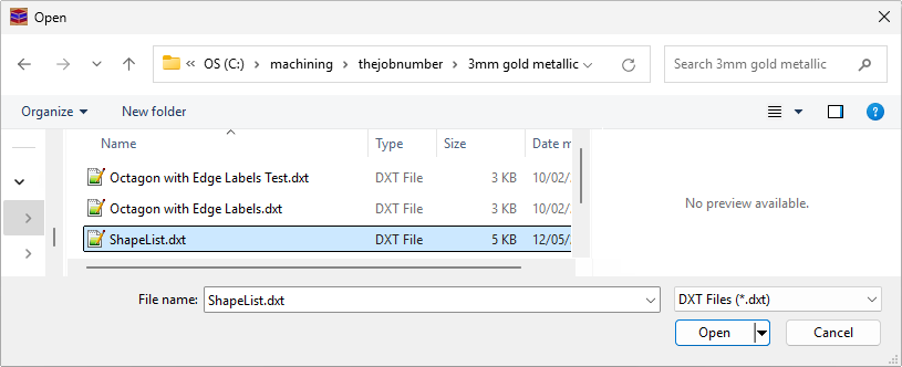
The file to process is normally found under the Machining directory of your C drive.
The location of the List Files exported from ShapeMaster will be shown (as per image below) when it has finished creating them. Each material used in your drawing will be separated into different folders, which can be brought in to EzyNest for nesting by selecting the .dxt file for the material you want to nest.
In this example, we have imported the file ShapeList.dxt located in the 3mm gold metallic (material) folder.
 It is recommended to nest only one .dxt file / material at a time.
This button will remove all imported .dxt files and clear the list of parts.
If the checkbox is turned on for an item in the list, it will be included in the nesting, otherwise it will be omitted when the job is processed.
Identifies the part that has been imported to the Parts List that will be nested.
The width, length and thickness of the part to be nested.
The type of material that was selected in ShapeMaster for this part.
In your drawing in ShapeMaster, each shape has an ID number. The Unit Number in the Parts List is the same as the ID number in ShapeMaster and helps to cross reference between ShapeMaster and EzyNest, for easier identification of each part.
Starting as 1 by default for each part, this is the number of times that each part will be included in the nest. This number can be no less than 1 but can be adjusted to any number that you require. This is a useful option when you are needing to make multiple copies of the same part.
If this checkbox is ticked, it will allow the part to be rotated when positioning it on the nest. The angle at which it may be rotated is specified on the Processing tab as the Angle Steps value. It is recommended to have this option turned off for grained material.
This is the angle at which the part will be positioned on the nest if the Allow Rotate checkbox is unticked. Commonly set for grained material, it comes through already set from ShapeMaster, as the orientation of the part has been specified during the design process.
If the parts are being cut out of a grained or patterned material, it is important that they are oriented correctly when nested.
This is determined by the Grained indicator on the chosen door material. It is assumed that the grain (or pattern) will always be vertical on the door (if this is not the desired result then simply switch the grain on the chosen material).
If the Grained indicator is:
The Grained indicator is represented by a combination of the Allow Rotate and Rotation Angle columns.
